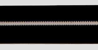
One of the methods developed in the 1920s for recording audio for movies was the variable area optical sound track. Photographic film stock was exposed to light modulated by the signal to be recorded. When a positive was printed the result was a clear area of varying width. The photo actually shows a piece of film recorded by the Philips-Miller, apparently a recording of a constant frequency. Playback is achieved by projecting a narrow slit of light onto the film and detecting the amount of light passing through using a photo-electric cell. A recording method like that used for cinema films, which required time for the photographic film to be processed before the recording could be played, would not have been suitable for broadcast use. Instead of using the optical/chemical method the Philips-Miller machine recorded mechanically.
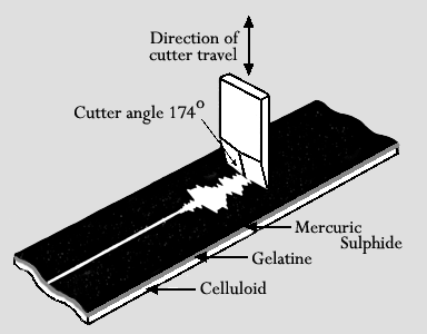
Some early experimenters had attempted to record on film using lateral cuts, but it was J. A. Miller of Flushing, N.Y. who developed the vertical cut idea in 1931. The following year he reached an agreement with the Philips research laboratory at Eindhoven on the use of his patents and further development work.
Philips provided some experimental equipment for the BBC to test in November 1934 and a preliminary quotation was made the following January. The equipment was priced at £4500 and the running costs would have been £20 per hour. In February 1936, and after some negotiating, a six month trial
Maida Vale
The building housing Maida Vale Studios began as
a roller skating rink c.1914. It was acquired by the BBC in 1934. Five
studios were built within the shell (a sixth added much later). It also
housed several recording channels, there because of lack of space at Broadcasting
House.
Problems soon became apparent. Imperfections in the film could produce spurious modulations and distortion. There was a breakdown during transmission and the machine had to be taken out of service to allow the engineers time to sort out the problems. It was back in use by October and then gave excellent results. Even at £7 per hour the running costs were considered to be quite high. This made the machine inappropriate for use on the Empire Service where the superior quality would be wasted on short-wave reception.
By this time, direct-cut discs were becoming established and producers were enjoying the ability to easily and rapidly pick out a section of a recording without having to spool through film or tape. But the Philips-Miller had considerable advantages when it came to making a permanent recording of a programme. It was cheaper than processed discs and offered better quality, negligible deterioration after repeated plays, superior reliability and the possibility of editing.
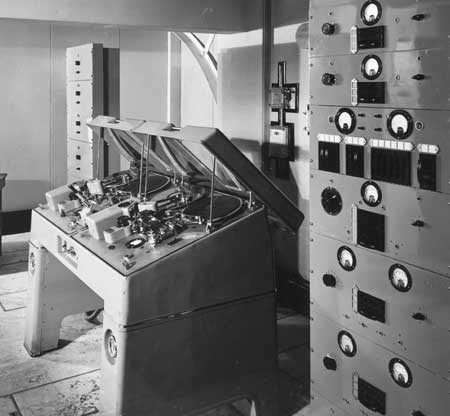
Recordings requiring the highest quality were still made at 32 cm/sec, but other recordings used the new, lower speed, albeit with some loss at frequencies above 4kHz. A few weeks were left before making a second recording on a film in case editing of the first programme was required. At the higher recording speed a spool ran for fifteen minutes.

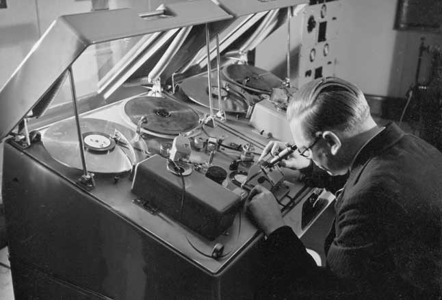
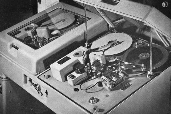
Each installation consisted of two combined machines placed side by side in a single unit to form a complete channel capable of continuous recording or
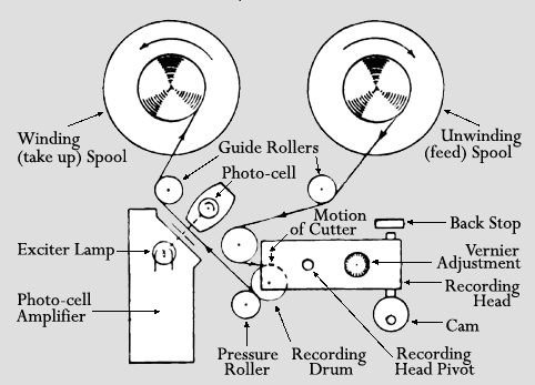
The main drive consisted of a 3-phase synchronous motor which drove the recording drum through a heavy flywheel.
Some machines used the same motor to drive the spools, through friction clutches which were regulated by pivoted levers resting on the outside of the spools. Other machines used two extra motors to drive the spools.

Some method of removing the swarf created by the cutting process would have been required. In this photo there appears to be a tube running from the recording head towards the right hand spool - this is probably part of a vacuum system.
In order to drive the film a rubber-faced pressure roller pressed it against the recording drum. Early attempts to use perforated film driven by sprockets, like cinema film, had resulted in unacceptable flutter.
The recording head consisted of a brass block with the electro-mechanical movement at one end and a micrometer screw adjustment, used to control the depth of cut, at the other. There was an automatic device which withdrew the cutter to produce minimum width of cut during silent periods, thus reducing noise.
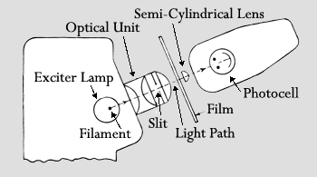
The output of the photocell was very small so a single valve pre-amplifier was built into the machine. The valve was mounted immediately behind the photocell, the remaining components were situated in the exciter lamp housing. The repro amplifier itself had a response which rose by about 10dB from 1kHz to 8kHz and was bay mounted. It was possible to playback during the recording process, thus allowing a check to be made on the quality.
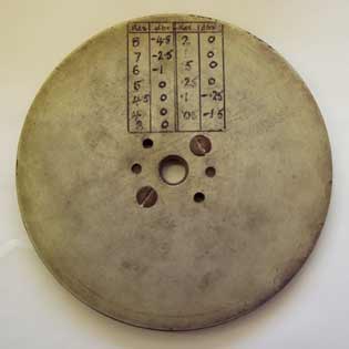
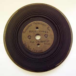
These pictures show a surviving spool of film, photos from Neil Wilson of the Washford Radio Museum. Clearly a test film it is labelled 'Standard frequency run' and dated 27th June 1944.
