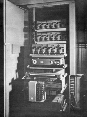
The supply cabinet containing the mains isolators and relays which allowed the desk to be powered from a push button on the control desk or directly from the supply cabinet. The system also made it possible for the desk to be powered up in, or switched to, the transmission condition by a red-light signal from the control room, a facility that sadly was unique to Type A. If it had been retained on later types of desk it would have saved many an SM from the embarrassment of going on-air in rehearsal condition and having talkback accidentally broadcast!
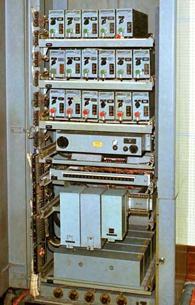
The Control Cabinet (right) held all the amplifiers and relays. The amplifiers were all identical and coded AMC/2 (Amplifier, Microphone/2). They had a maximum gain of 50dB which was adjustable in 10dB steps and used a single AC/SP3 valve (said to stand for 'alternating current / straight pentode, number three'). This was an indirectly heated type; the heater needing 4 volts AC at 1 amp, on a 7-pin base with the grid brought out to a top cap. The amplifiers could be replaced by removing the single multi-way plug at the front, sliding out the faulty one and sliding in a new one. The cabinet was lockable (although most were left unlocked) and on the production models a small door in the right-hand pillar gave access to a small jackfield for cross plugging purposes. This was very inconvenient in some studios where the cabinet was not on the same floor as the desk as in 3A and 6A in the early sixties, for example.
The colour shot shows part of the cabinet of one of the Portland Place studios at the end of its life.
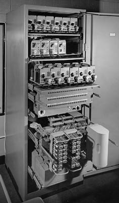
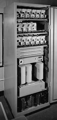
The next two views show the apparatus cabinet of the prototype Type A, showing mic amps, jackfield (not yet in the right hand pillar), monitoring amp, relay boxes, mains units and swivelling connection strips.
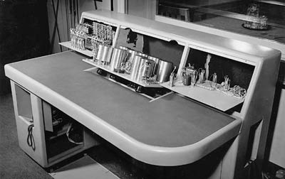
The left-hand one carried amplifier changeover keys which allowed any amplifier to be replaced by a spare. This switching was so good that operating a changeover key was virtually undetectable if both amplifiers were OK. It seems there was a great deal of concern about the reliability of the amplifiers and thus the comprehensive provision of spares and switched changeover facilities. Whereas these days if an amplifier works OK for the first year of its operation it will probably carry on working for the next 25 years or more, the components in 1940's valve amplifiers were not so reliable. The 1932 control room had just 31 'A' amplifiers for the entire needs of Broadcasting House but 15 years later a Mark V desk had a total of 16 'A' amplifiers serving just one studio. However, I cannot recall ever having an amplifier fault even on the venerable Type A desks still in use in the late 60's / early 70's.
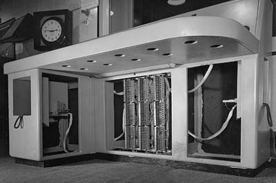
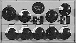
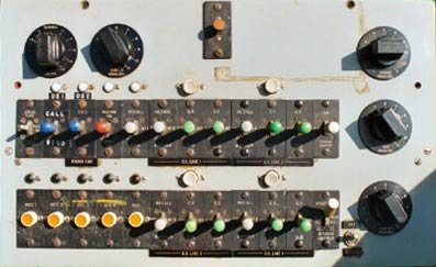
The novel features of the Type A
There were many completely new design features in the Type A desk.
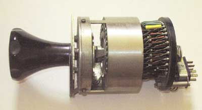
All the channel faders were of the balanced bridged-T type and at any setting had an input and output impedance of 600 ohms. In the MX/18 and in 1932 vintage desks, the faders were simply a variable series resistance in each leg and when paralleled to enable mixing to take place, there was interaction between each channel causing variations in volume of one channel when another was faded in. The Type A fader avoided this interaction. The faders could be removed for cleaning by releasing a simple sprung catch below each one. (Note that the 'control' potentiometers in the 1932 control room were however constant impedance).
Echo Facilities
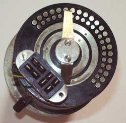
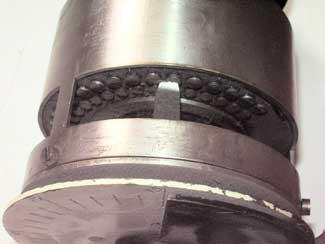
On the larger desks any channel could be fed to an echo room. (The BBC has always used the word echo to refer to what is actually 'reverberation'). This was done by means of a 9 position 'Echo Mixture Switch' on the left-hand panel of the desk. In position 1, the channel was fed directly to the main fader with nothing fed to echo. Turning the switch fed increasing amounts to echo until at position 5, direct and echo were equal. From position 5 onwards the direct feed was attenuated until at position 9 the whole channel output was fed to echo. The echo room microphone arrived back at the desk where it was treated like any other microphone (except of course it could not be fed to echo!) and was mixed in to the desk output via an 'echo cut' key. The Independent/Narrator's channel could not have echo. The pre-production desk had echo mixture switches, which was unusual for this size of desk.
Emergency Arrangements and Two-way Working (Clean Feed)
These were later additions and modification to Type A. Normally when there is a contribution from an Outside Source to a programme, the output of the studio desk can be fed back to the source for cue and talkback purposes. This straightforward approach will fail if the Outside Source is such a distance away that there is a delay in the source receiving the programme. It is virtually impossible to speak if you can hear your own voice a fraction of a second after you have spoken. What is needed is a feed of programme that does not include the outside source. There is also a problem if the programme being simultaneously produced by two different broadcasters with mixing of microphones with tapes and outside sources taking place at both ends. Each studio needs a feed that includes all of the distant studio's output but must not get back their own contribution to that studio. The BBC named this type of feed 'clean feed', whereas other broadcasters called it 'mix-minus'. (Unfortunately 'clean feed' is also used to mean a feed of a concert or other event without the BBC's announcements but this rarely has caused confusion). Type A was not designed for this and had to be modified when programmes needing the facilities described became commonplace. The modifications were somewhat messy as the channel normally associated with Mic 4 could not be used if clean feed was in use as its amplifier was 'borrowed' to amplify the clean feed to line level, the incoming source was tied to its channel and could not be cross-plugged, the source did not pass through the main fader, there was no way in the studio of correcting low-level from the source and, as originally implemented, transmission talkback to the source was not possible. As a by-product of the modifications a low-level mixed output became available when clean feed was not in use and this was connected to an 'emergency' line to Control Room. This facility was discontinued when a further modification made it possible to switch between clean feed and clean feed with transmission talkback. There was also an 'Emergency' Mic socket in Type A studios that went direct to Control Room as a final 'belt and braces' back-up. I don't recall any instance of either emergency facility ever being used which says a lot for the reliability of the desk in general and the amplifiers in particular.
