Introduction.
In addition to the standard bays, each studio is provided with a standard desk, Type DK/1601A, on which is mounted a Mixer Unit, Type MX/18, and Amplifier, Type OBA/8. In most cases this desk is located in the Control Cubicle adjacent to the studio but where no cubicle is available the desk is fitted in the studio itself, the gain of the amplifier being adjusted to a fixed predetermined level. Each studio or cubicle also contains a gramophone desk, Type TD/3702B, which is normally supplemented by an additional single turntable unit of the Presto type.
At some of the London area studio centres provision is made for the exercising of presentation and technical control over given programme networks. This provision takes the form of what is known as a Continuity Suite, which consists of a studio, called the Continuity Studio, and a control point, known as the Continuity Room. Facilities are available in the continuity room for the selection of its own programme sources which may consist of the continuity studio output or any other source obtained from the Control Room. The primary object of the continuity suite is to ensure the maximum possible co-operation between presentation and technical staffs.
It should be observed that although the control of programmes from a continuity suite is effected in the continuity room, the Control Room exercises a technical supervisory control over programmes originating at or passing through that particular studio centre. This is essential since the Control Room functions as the distribution point for in-coming and out-going programme and control lines. It is also the controlling point for programmes not being controlled in a control cubicle or continuity room, but which are originating at that studio centre for distribution to other programme networks or to the local recording room. The Control Room also functions as a stand-by for the continuity room and is responsible for housephone circuit distribution.
The housephone circuits are arranged on a system of floor distribution designated Ring Mains, there being other forms of ring main distribution to recording channels and miscellaneous points where a number of "on tap" programme sources are required.
At some of the larger studio centres, a Recording Suite is provided comprising a Studio, a Mixer Room containing three twin turntable gramophone desks, together with one or more Recording Rooms. Such a suite is intended to provide facilities for recording talks and building up composite recorded programmes and for close cooperation between technical and programme staffs.
It is not intended in this specific instruction to describe each component part of the equipment, since separate instructions covering such detail will be issued at an early date. This instruction is therefore confined to general considerations, dealing with schematic layout of equipment, special attention being given to programme distribution circuits linking the studio outputs to the Post Office lines.
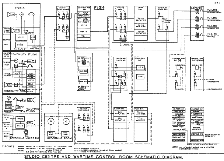
OUTLINE OF GENERAL SCHEME (Fig.4).
Considering the scheme as a whole, the studio amplifier outputs are taken to a Multi-Distribution Bay in the Control Room, thence to the Control Position Bays. The outputs from the control position bay amplifiers are taken to another multi-distribution bay, at which point these outputs are distributed to the inputs of a number of Trap Valve amplifiers. The output from the control position bay amplifier in the continuity room is treated in precisely the same way and is taken to the second multi-distribution bay. The trap valve amplifiers are mounted on separate apparatus bays and are divided into two groups, one of which feeds the outgoing Post Office lines, the other group feeding recording rooms and ring main circuits. Incoming circuits, such as S.B. or O.B. lines, are taken to separate bays and plugged as required to the control position bays or "D" amplifier inputs. The general scheme is shown diagrammatically in Fig.4. (below, or click on the image for a larger version in a new browser tab)
STUDIO EQUIPMENT.
1. General Purpose Studio (Fig.1).
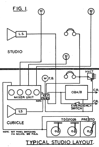
The cubicle also contains a standard twin turntable Gramophone Unit, Type TD/3702B, the output of which is tied to one of the mixer inputs. In addition a single turntable desk of the Presto type is provided, its output being paralleled with the output of the TD/3702B.
The gramophone desk, Type TD/3702B, comprises two electrically-driven turntables, with speed controls and indicators, together with two B.T.H. pick-ups mounted on parallel tracking arms. The output of each pick-up is taken via a correction unit to a fader on the front of the desk. An additional fader is provided for the studio microphone. This desk is a modification of the original desk, Type TD/7, which is now obsolete.
The Presto single turntable desk comprises an electrically-driven turntable which is capable of rotating at either 78 R.P.M. or 33 1/3 R.P.M. The pickup associated with the desk is wired to a local amplifier housed within the cabinet, the output of which is attenuated to the same level as that obtained from the output of the TD/3702B, namely -70db. The purpose of this desk is primarily to provide facilities for reproducing discs recorded at a speed of 33 1/3 R.P.M., but it also provides additional facilities for dealing with records or discs recorded at 78 R.P.M.
The output of the OBA/8 is taken to the Programme Source multi-distribution bay in the Control Room, at which point it is distributed to the control position bays in the Control Room and to the continuity rooms, where they exist.
In the event of a failure of the local studio amplifier, an Emergency Switch, fitted at the back of the desk, DK/1601A is put to EMERGENCY position, connecting the output of the MX/18 direct to Control Room. The termination of the emergency circuit appears on the Incoming Lines Bay, at which point it can be readily plugged to the input of a "D" amplifier, the output of which takes the place of the original programme source.
2. Control Cubicle.
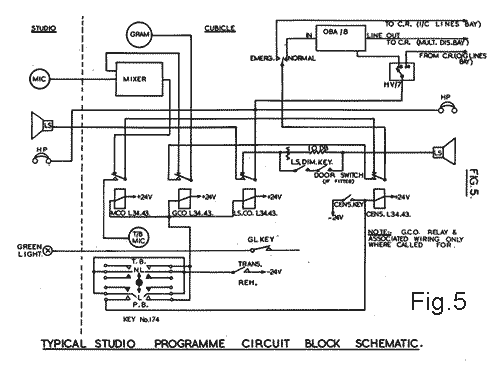
The Control Cubicle desk is fitted with a toggle switch and four lever type keys (Fig.5), which perform the following functions:-
This key is provided to enable the volume from the loudspeaker to be reduced during telephone conversations, etc. A 10db. attenuator is placed in series with the cubicle loudspeaker input. With the dimming key in its normal position, this attenuator is short-circuited. The operation of the key to the dim position removes the short circuit and reduces the volume accordingly.
In some studios, an additional switch is included, which removes the attenuator short-circuit each time the studio door is opened, the switch being automatically operated by the movement of the door. The device is fitted to prevent howl back between the studio microphone and the cubicle loudspeaker.
(b) Cue Key.
The function of this key is to operate the local Studio Green Light and is independent of the normal Red Light signal circuits operated from control positions.
(c) Toggle Switch. Rehearsal-Transmission.
The REHEARSAL-TRANSMISSION toggle switch acts as a master control to the Talkback-Playback key. In the TRANS. position, -24 volts is isolated from the talkback key, rendering it inoperative irrespective of its position. In the REH. position -24 volts is connected to the talkback key travellers.
(d) Talkback-Playback Key.
This key is for use during rehearsals only. In the Talkback position, the Microphone Change over (M.C.O.) relay is operated, switching the OBA/8 input from the MX/18 output to the cubicle talkback microphone: At the same time, the Loudspeaker Change Over (L.S.C.O.) Relay switches the output of the HV/7 from the cubicle loudspeaker to the studio loudspeaker. The talkback microphone is thus connected via the OBA/8 and HV/7 to the studio loudspeaker. The HV/7 unit must be set to position 8, which is connected to the monitoring output of the OBA/8. In the talkback (TB) position, the key is non-locking, to facilitate two-way conversation between studio and cubicle.
The function of the Playback circuit is to enable gramophone records to be played back from the cubicle to the studio loudspeaker without the setting up of special circuits in the Control Room. For this purpose the HV/7 switch is set to position 8. In the playback (PB) position, the Censor (CENS.) and, when fitted, Gramophone Change Over (G.C.O.) relays are operated, connecting the output of the gramophone unit to the OBA/8 input. The L.S.C.O. Relay also operates, connecting the output of the HV/7 to the studio loudspeaker. The M.C.O. Relay is energised in this position, but the T.B. microphone circuit is broken by the operation of the Censor relay. By setting the HV/7 unit to positions 1-7, any one of the main programme networks can be heard on the studio loudspeaker. Any other programme passing through the Control Room can be plugged, in the Control Room, and made available on position 9 of the studio HV/7.
(e) The Censor Key.
The function of this key is to interrupt the programme input to the OBA/8 as programme censorship demands. When operated, the key connects -24V to the Censor relay, all other relays remaining inoperative.
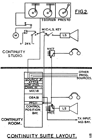
3 . The Continuity Suite (Figs. 2, 4 and 14).
The Continuity Suite comprises the Continuity Studio and the Continuity Room. The studio contains a microphone and twin turntable unit, the output of which is taken at low level to the source (Low Level) Input Jacks on the control position bay in the continuity room. The studio is used exclusively for presentation and programme linking announcements, the gramophone unit being provided for interludes. The continuity room contains a standard control position bay, the programme output of which is fed to the T.V. Input multi-distribution bay in the Control Room. Provision is made for the injection of G.T.S. Or Interval Signal into the input of the OBA/8 as occasion demands.
Further details of continuity room equipment are given under the heading "Control Position Bay" (Section B), and a circuit diagram appears in Fig.13.
4. Recording Suite (Figs. 3 and 4).
At some studio centres a Recording Suite has been provided, the function of which is to facilitate close cooperation between Recorded Programme and Technical staffs. The arrangement permits the use of a Studio and Mixer Room over an extended period without tying up studios and equipment which might well be required for other purposes.
A typical recording suite consists of a studio, mixer room and two recording rooms (Fig.3). The operational responsibility for the suite is divided between Control Room and Recording Section staffs, this Instruction being mainly concerned with the studio and mixer room layout.
The Recording Studio (Fig.3).
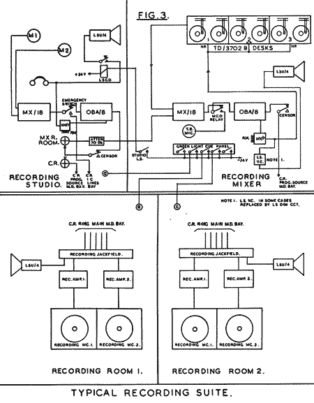
The studio is equipped with a Loudspeaker Unit, LSU/4, the input of which is only connected to the HV/7 Unit when the studio L.S. key in the mixer room is depressed. Housephone circuits are available on the HV/7 Unit, the LS circuit also being wired from this point. The control desk is provided with normal studio signalling, censor and emergency switching, the emergency switch being mounted under the desk.
The Recording Mixer Room (Fig.3).
The Recording Mixer Room is equipped with three twin turntable Gramophone Desks, Type TD/3702B , and a Control Desk, Type DK/1601A. The latter desk is fully equipped with a Mixer Unit, MX/18, Amplifier OBA/8 and normal studio signalling, talkback and emergency switching. Studio green light cue signalling is provided, the circuits being wired to the recording studio and the recording rooms.
Referring to Fig.3, it will be seen that the microphone circuit from the studio is fed from the attenuated output of the studio OBA/8 Amplifier into the Recording Mixer, where it is connected to the mixer unit MX/18. The common output of the three gramophone desks (TD/3702B) is also taken to the mixer unit input. The output of the MX/18 is taken to Control Room via the M.C.O. Relay, OBA/8 Amplifier and Censor Key. The monitoring output of the OBA/8 is fed via the HV/7 unit back to the gramophone desks, making head phone listening available at each desk. The HV/7 unit also feeds the loudspeaker unit LSU/4 via a volume control. In some cases the volume control is replaced by the standard LS dimming circuit. This latter arrangement is likely to be more general.
The switching for the M.C.O. Relay is not shown on this diagram, but is similar to the talkback switching arrangements shown in Fig.5 (above). That is to say, the operation of the talkback key connects the recording mixer talkback microphone to the loudspeaker in the studio.
SECTION B. STANDARD BAY ASSEMBLIES.
The following description of the Standard Apparatus Bays is given in the sequence order obtaining for the programme path from source to outgoing Post Office lines. It must be borne in mind that a very considerable amount of inter-bay wiring is involved in the linking of apparatus on the various bays.
In order to standardise on the method of interbay wiring, modern practice is for all apparatus to be wired via a Main Distribution Frame (M.D.F.) so that any modification which at any time may become necessary can be effected simply by altering the jumper wiring on this distribution frame.
Multi-Distribution Bay (Fig.6). General Description.
This bay provides for the connection of any output circuit (e.g. output of an OBA/8) to the input of one or more other circuits (e.g. inputs to trap valves), the arrangement being such that, where one output feeds several inputs, a different output may be quickly substituted for the original, all the associated individual inputs being switched over together to the new output. All the circuits associated with the bay are terminated on jacks, so that under any desired condition, any or all individual inputs may be removed from circuit if necessary.
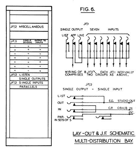
The second group consists of eight rows of jacks, each row being wired in two separate sections of ten jacks. The first three jacks are wired horizontally on the familiar Three-jack system and are labelled Listen, Apparatus, Line. The apparatus jack carries the output of the programme source feeding the bay on its outers, the listen jack being parallelled across in the normal way. The inners of the apparatus jack are wired to the inners of the line jack and the outers of the line jack to the parallelled inners of the remaining seven jacks. These jacks constitute the inputs to the succeeding stage in the Programme Chain, such inputs being connected to the outers of the seven jacks.
From this it will be seen that each of these eight rows of jacks comprises two sources, there being seven distribution points for each source. In special cases a small alteration is made to the bay wiring which enables one source to feed the remaining 17 jacks in the row.
The three rows of jacks below these are wired vertically on the "three-jack" system, but in this case, each output line jack feeds only one input. With this arrangement, each of 20 outputs is wired to a single input with a listen jack across each output. In the event of a condition arising where it is required for any one of these outputs to be connected to more than one input, use is made of the bottom row of jacks, which is divided into four strips of five parallel jacks.
Since it is an essential condition for the working of these bays that all output levels should be the same, it has been possible to wire the bays with multi-core cables.
It must be clearly understood that although all Multi-Distribution Bay Assemblies are identical in design, the uses to which they are put vary according to the service required. Thus there are multi-distribution bays for programme source distribution, programme distribution to trap valve inputs, etc.
Multi-Distribution Bay (Programme Source) (Fig.7).
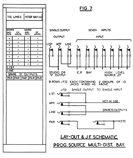
Fig.8 shows the programme chain to the point where it leaves this bay. It should be noticed that all programmes passing through this bay are at zero level.

Control Position Bay. (Fig.9).
The Control Position Bay is so designed that it can be used in either a main Control Room or in a continuity room. Its main functions can be summarised as follows:-
- Connecting any one of twenty programme sources to any of the four input channels of a mixer unit.
- Mixing these four selected programme sources as required to maintain the continuity of the programme service.
- Controlling the programme passing through the main amplifier to specified levels as indicated by the Peak Programme Meter.
- Injecting into the programme chain various signals, e.g. Greenwich Time Signal or Interval Signal.
- Providing pre-fade listening facilities across the mixer input jacks.
- Providing monitoring facilities with provision for comprehensive checking on H.P. or LS circuits.
- Providing signalling circuits to all local studios.
- Providing terminations for control lines and telephone indicators.
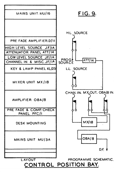
The function of the individual panels, starting from the top, is as follows:-
MAINS SUPPLY UNIT MU/16.
This unit supplies L.T. (A.C.) and H.T. (Rectified A.C.) to the Monitor Amplifier D/11. The unit is sometimes mounted at the bottom of the bay.
PFL AMPLIFIER D/11. The purpose of this amplifier is to raise the input level of -70 dB to a level suitable for H.P. or LS input, i.e. to zero dB Its input is connected to the travellers of four plunger keys on the PFC/1 panel, its output being tied to the comprehensive check keys on the same panel.
HIGH-LEVEL SOURCE JACKFIELD.
This jackfield contains jacks for headphone listening across the lines from the programme source multi-distribution bay. The inners of the jacks are wired to an attenuator panel, a number of jacks being connected to 70db. attenuators, each of which corresponds to the output of a local studio. Other jacks are wired to attenuators connected to tie lines to the O.B. terminations bay and to the incoming lines bay, known as O.B. and S.B. tie lines respectively. These attenuators introduce a loss of 25db., this value being determined by the equalized level obtained from the O.B. and S.B. incoming lines which is being standardized at -45db. Until this standardization is completed, the attenuators at some centres introduce a loss of 20db. in the case of O.B. Tie lines, and a pre-determined loss in the case of S.B. Tie lines. In the rare case when the equalized equivalent of the incoming line is below -45 dB, the equalizer output may be plugged to the input of a "D" amplifier, the output of which will be plugged to the control position in place of the equalizer output, or alternatively, the gain of the OBA/8 amplifier on the control position may be increased.
There are 20 programme sources available on this jackfield, attenuation of each individual source being such that the output of the attenuator presents a level of -70db. to the mixer input. Space has been left on the bay for the provision of additional source jackfields should this become necessary.
ATTENUATOR PANEL AT/14.
This panel contains the various attenuators mentioned in the preceding paragraph. The output of each attenuator is taken to the low level jackfield immediately below the attenuator panel.
These attenuators have two important uses. Firstly, they enable the studio programme source to be brought into the bay at zero level. This is particularly advantageous in avoiding cross talk between programme sources and other high level circuits which would be more likely to obtain were the programme sources fed into the bay at a level of -70db. Secondly, the attenuators form a means of separation between control position bays where programme sources are multipled to a number of control positions. Thus, a studio output which is fed into two control positions passes through a 70db. attenuator in each case, so that between the two mixer inputs, there is an effective separation of 140 dB, and in the case of an O.B. programme, which will be passed through a 25db. attenuator in each case, there is a separation of 50db. This separation is particularly useful in avoiding cross talk between one control position and another during mixing operations.
LOW-LEVEL JACKFIELD.
Since this jackfield carries the outputs of the various attenuators, it should be clear that its function is to provide access to a source level of -70db. for plugging to the channel inputs of the mixer unit MX/18. In a few cases, such as Big Ben circuits, the low level jacks are normalled to channel inputs.
CHANNEL INPUT JACKFIELD.
The purpose of this jackfield is self-explanatory. The outer of each each channel input jack is wired to the respective input of the mixer unit and to the pre-fade listen keys. This jackfield also contains a number of miscellaneous jacks, the most important of which is the output jack from the mixer unit and the input jack to the OBA/8 amplifier. A schematic of the jackfield arrangements is given in Fig.9.
KEY AND LAMP PANEL (KL/23). - STUDlO SIGNALLING (Fig.11).
This panel contains the studio signalling keys and return lights for orthodox Studio-Control signalling. Provision is made for 20 of these signalling circuits and in cases where a number of control position bays are installed in a Control Room, the 20 signalling circuits are parallelled to the individual control position bays. Under these conditions the operation of the signalling key brings up a red light on all the control position bays simultaneously while the operation of the studio buzzer push button will sound a buzzer in the Control Room and bring up a green light over the appropriate key on each control position bay. The green light is cancelled by the operation of the signalling key in the reverse direction. The schematic arrangement is indicated in Fig.11.
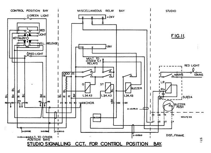
From this drawing it will be seen that when a studio buzzer push is operated, -24 volts is applied to the ST relay, the top contacts of which close and supply -24 volts to the buzzer relay. The bottom contacts of the ST relay close simultaneously and supply -24 volts to the G relay, the top contacts of which connect -24 volts to the green light on the control position bay. The bottom contacts of the G relay close an alternative path to -24 volts and thus constitute a "hold on" circuit when the buzzer push is released. To disengage the green light, the signalling key is moved to the non-locking "up" position, closing the bottom contacts of the key. Now it will be seen that the positive side of the G relay coil is fed from the positive 24 volt fuse termination strip via a 1000 ohm resistance so that it is possible to short circuit the relay coil without putting a short circuit direct across the 24 volt supply. This, in effect, is what happens when the bottom contacts of the signalling key are closed. The relay side of the 1000 ohm resistance is connected to -24 volts thus disengaging the G relay and breaking the -24 volt circuit to the green light.
When the signalling key is put to the locking "down" position, the upper contacts of the key are closed, connecting -24 volts to the control position red light associated with the studio concerned and also to the LR relay in the studio the contacts of which, when closed, complete the mains supply circuit to the studio red light.
MIXER UNIT (MX/18).
This is a standard four-channel Mixer Unit designed to provide facilities for setting up four programme channels simultaneously. The operation of the mixer channels has been facilitated by the provision of pre-fade listen keys, by means of which any programme source available on the mixer can be readily switched to the monitoring circuit. This is particularly useful for linking up programmes, since it is possible for announcements or cues from another network to be heard, thus making precision of entry or re-entry to a programme a relatively simple operation.
The output from the mixer unit is taken back to the channel input and miscellaneous jackfield, the connection being made to the outers of the mixer output jack, the inners of the jack being connected to the inners of the OBA/8 input jack, the outers of the OBA/8 input jack being wired to the input of the OBA/8 amplifier itself. A description and circuit diagram of this unit is given in Technical Instructions, Volume 1, Item 7.
AMPLIFIER OBA/8.
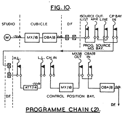
This Amplifier is identical to that described in Technical Instructions, Volume 1, Item 7, except that the monitoring output has been modified in order that loudspeaker amplifiers of varying input impedances may be employed without affecting the readings of the peak programme meter. The input is fed from the output of the mixer unit. The line output is fed to the Control Room distribution frame at a level of zero dB
Fig.10 shows the programme path from source to control position bay output. The monitor output of the amplifier is taken to the various checking circuits, described in the next paragraph.
PRE-FADE AND COMPREHENSIVE CHECK PANEL, PFC/1 (Fig.12).
The switches and keys on this panel provide facilities for comprehensive checking over all the circuits normally associated with the control position and for the injection of interval signals, etc., into the programme. The panel also contains five jacks with indicators which are terminated on a control line bay in the Control Room and can therefore be extended to any O.B. Or S.B. control line. The four plunger type keys are connected to the mixer input circuits. The depression of any one of them connects the mixer input to which it corresponds to the input of the monitoring amplifier, D/11. In the case of the Control Room, the output of the D/11 is taken to the H.P. monitoring jacks only, whereas in the continuity room, it is taken to the H.P. monitoring jacks and also to the loudspeaker via position 8 of the HV/7 unit. In both cases, the circuit is wired via the comprehensive check keys.
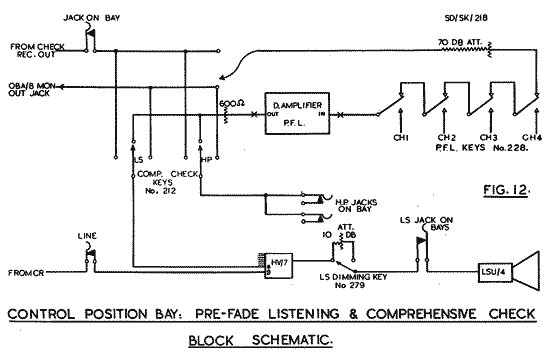
In the "up" position labelled OBA/8, the monitoring circuit is connected direct to the monitoring output of the OBA/8 on the control position.
In the central position, labelled OBA/8 and PF, the attenuated monitoring output of the OBA/8 is available via the pre-fade amplifier and, in this position, the operation of any plunger type key breaks this output, replacing it by the channel input appertaining to that key. In some cases, the attenuated OBA/8 monitoring output may be replaced by the attenuated output of the check receiver. The central position of the key will then be labelled CK.R. And PF., the circuit otherwise remaining the same. This condition obtains where specific instructions are laid down that monitoring shall be carried out on the check receiver.
In the "down" position, labelled CK.R., The monitoring circuits are connected direct to the output of the check receiver normally used with that specific control position.
In the case of the LS comprehensive check key, this will only be used in continuity rooms where it supplements the facilities provided by the H.P. checking key. Thus, if it be required to maintain a constant LS check on the output of a given check receiver, it is possible to retain the H.P. comprehensive check facilities without interrupting the constant check. The arrangement is obviously quite flexible.
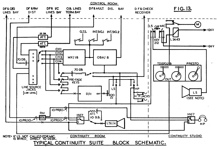
A complete block schematic for a continuity suite is given in Fig.13. From this it will be seen that the studio microphone is connected to the TD/3702B desk via a change-over relay which is operated by the L.S.-Mic. Key. When the key is switched to the MIC. Position, the relay is energized, completing the microphone circuit via the TD/3702B desk to the control position bay jackfield. When the key is connected to the LS position, the relay breaks the microphone circuit, the studio LS circuit being completed via the key contacts to the continuity room comprehensive check key travellers. In the central position of the key neither microphone nor LS circuits are connected. It should be remembered that the turntable desk is provided with a fade unit for the microphone, in addition to the fade unit for the two turntables. The Presto gramophone unit is connected direct to the output line from the gramophone desk. The continuity room is provided with full comprehensive checking facilities, which have been described previously. In the drawing the pre-fade keys are shown as two-point switches and the checking keys as three-point switches. In practice, the pre-fade keys are of the plunger type No. 228 and the comprehensive checking keys of the lever type No. 212.
The Unit BT/6 shown on the drawing, constitutes the junction box for ring main floor distribution.
The three keys labelled G.T.S., Interval Signal 1 and Interval Signal 2, are connected between the mixer output and the OBA/8 input, so that the operation of any one of them injects the required signal into the programme. The arrangement permits the superimposing of the Greenwich Time Signal on a given programme, or the interposing of interval signal between two consecutive programmes without interruption of other programme circuits. In the case of the interval signal keys, provision is made for applying -24 volts to relays which, when energised, switch on the motor of the required interval signal turntable.
Multi-Distribution Bay. (Trap Valve Input) (Fig.14).
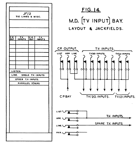
The TV/20 amplifiers are normally used for feeding programme to outgoing lines and have an output impedance of 600 ohms and maximum gain of 10db. continually adjustable.
Since the output of the control position OBA/8 terminates on the apparatus jack of the JF/1, its inners being normalled to the inners of the line jacks feeding the various trap valves, in the event of the failure of an OBA/8, the output of a spare control position can be substituted quickly by the simple operation of cross-plugging the output (Apparatus) jack of the spare position to the line jack of the output effected. In this manner all the trap valve inputs will be changed simultaneously.
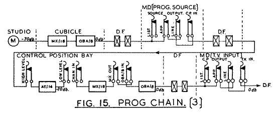
The arrangement of the jackfields for single distribution may vary to suit local requirements but, in general, will consist of facilities for connecting individual "D" outputs to individual trap valve inputs. Fig.15 shows the programme chain to the point where it leaves this bay.
Trap Valve (TV/20) Amplifier Bay (Fig.16).

This bay is designed to accommodate 6 Trap Valve Amplifiers, Type TV/20, and 6 mains units, Type MU/16. The Trap Valve Amplifier TV/20 is used to feed programme to the outgoing Post Office lines connecting up the S.B. system. The amplifier actually comprises two separate amplifiers mounted as a single unit, each of the amplifiers having two outputs. Thus each TV/20 has, in effect, two inputs and four outputs. In order to distinguish between the two sections of the unit, the sections are designated A and B. Thus the jacks corresponding to a given trap valve (say No.16) will be labelled as follows:-
| TV/20 No.16 | |||||
| ___________________________________________ | |||||
| INPUTS | OUTPUTS | ||||
| IN A | IN B | OUT A1 | OUT A2 | OUT B1 | OUT B2 |
The amplifier has an input impedance of 8,500 ohms and an output impedance of 600 ohms with a maximum gain of 10db. The working gain of each of the four outputs is continuously adjustable by means of a composition type volume control. From the foregoing it will be seen that the amplifier provides the same facilities in one unit as was previously obtained from four "C" amplifiers, thus saving considerable mounting space.
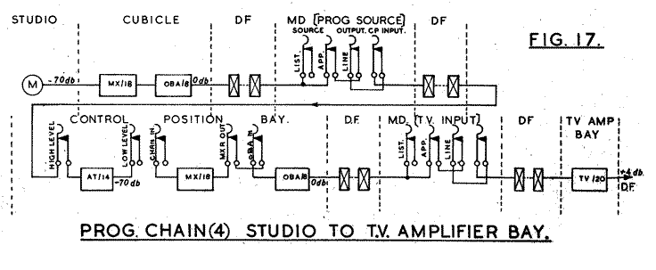
There are no break jacks on this apparatus bay, since the multiplicity of circuits would involve the use of so many jacks that, were they included, the number of units on each bay would be materially reduced. The trap valve input jacks appear on the Trap Valve Input multi-distribution bay and the output jacks on the Outgoing Lines bay. The bay layout is shown in Fig.16. The Programme Chain to the output of the bay is shown in Fig.17.
Trap Valve (TV/21) Amplifier Bay (Fig.18).

The input jacks of these amplifiers are extended to the control position bays and the output jacks to the ring main distribution bays. The input impedance of the amplifier is 1,200 ohms and the output impedance 5.3 ohms; the latter makes it suitable for feeding into a number of circuits without impedance conditions being affected. The nominal gain is pre-set at 0db. Or +4 dB, according to the working conditions required. There is no variable control of any kind on this amplifier.
Each of the mains units MU/16 supplies L.T. And H.T. to two amplifiers. The power supply to each amplifier is taken via a plug and socket panel, which is provided with a hum-dinging unit for each amplifier. This arrangement enables the power supply to be disconnected from one amplifier without affecting the other.
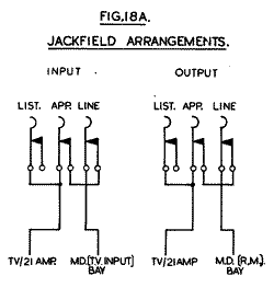
The bay lay-out and jackfield arrangement are shown in Figs.18 and 18A, programme distribution being shown in Fig.18B.

Outgoing Lines Bay (Figs. 19 and 20).
This bay performs the following functions:-
Connection of any output, such as a trap-valve amplifier output or "D" amplifier output, to any outgoing circuit such as outgoing music lines, individual lines to recording rooms, etc. It is thus the principal junction of high level sources and high level destinations. The Bay Assembly (see Fig.19) comprises:-

- 2 Jackfields JF/1A. Miscellaneous. This jackfield accommodates 40 jacks which can be used as tie lines to other bays, strips of parallels, etc., as required.
- 4 pairs of Jackfields JF/1A, accommodating trap valve amplifier outputs. Each pair of these jackfields accommodates 20 sources, each with listen jack.
- 4 pairs of Jackfields JF/1A. Outgoing circuits. Each of these jackfields accommodates 20 outgoing circuits, a listen jack being provided for each circuit.
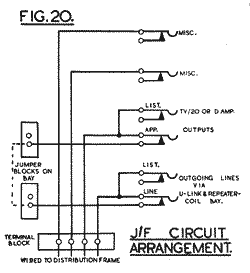
The inners of the outgoing circuit line jacks and of amplifier out apparatus jacks are brought to jumpering blocks on the bay so that, where particular sources are normally associated with particular lines, the inner circuits may be jumpered. This avoids excessive use of plugs and cords.
Since all the circuits on this bay are at high level (+4 dB), all wiring is carried out in multicore cables. The outgoing circuits are wired to the U-link and repeating coil bay via the distribution frames.
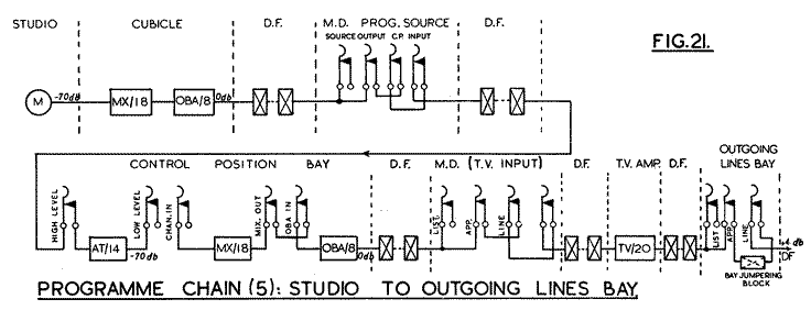
The programme path from source to the output of this bay is shown in Fig.21.
U-link and Repeating Coil Bay (Fig.22).

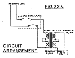
This bay assembly provides a termination point in the Control Room for the main Post Office cables carrying the S.B. music and control circuits.
The bay is intended for use at all premises having large Control Rooms. It is used in association with the incoming, outgoing and control lines and sometimes with O.B. line termination bays. It is fitted with a U-link panel which is permanently wired to the Post Office cables and repeating coils which are included in the line circuit as required.
The bay assembly (see Fig.22) comprises a link panel, LK/5, capable of taking up to three trunk test tablets, each of which will accommodate 24 lines, and 11 repeating coil mountings, RM/1, which provide space for mounting 66 repeating coils. All but 6 of the circuits on the link panel are wired via a repeating coil position to the bay terminal strips, although repeating coils are not fitted in the first instance, the wires being looped to the appropriate position. Repeating coils are then added on site as required, by cutting the looped wire and inserting the coil.
Where possible, on large installations, using two or more of these bays, the lines will be split so that high level or outgoing circuits will be on one bay and low level or incoming circuits on another bay. All bay wiring is carried out in individually screened pairs.
The programme path, from source to outgoing Post Office lines, is shown in Fig.23.

Incoming Lines Bay (Figs.24 and 25).
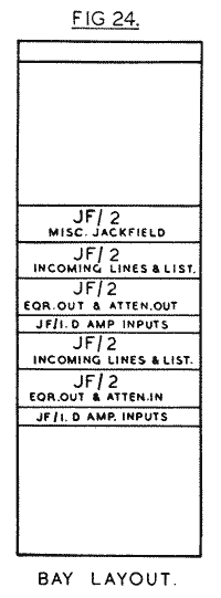
The Incoming Lines Bay (Fig.24) performs the following functions:-
- Provides jack terminations for the incoming music lines arriving from the distribution frame.
- Provides jack terminations for the outputs of the equalizers associated with these lines and for connecting the equalizers to the lines as required.
- Provides facilities for the equalized outputs of the lines to be distributed to their appropriate destinations.
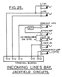
At some studio centres it is desirable to have two separate outputs available on each incoming line, to allow the plugging of that line to two control position bays without affecting the level. This is accomplished by means of a balanced resistance pad or, if the equalized equivalent of the line is too high, by means of a repeating coil having two outputs. This facility allows the second control position to take a consecutive programme on this same line without last minute plugging operations.
The attenuator on the incoming lines bay is designed to give a standard level (normally -45db.) at the attenuator output jack. In cases where the Atten. Out jack is not connected to the "D" input or to control position bay by inner to inner wiring, the circuits are, of course, completed by plugging.
For test purposes it may sometimes be desirable to remove an equalizer and Repeating Coil from the line, in which case the necessary operation is carried out on the U-link and Repeating Coil Bay.
Since many of the incoming circuits will be at relatively low level, the wiring to the bay is carried by individual screened pair cables.
A diagram showing the programme path from incoming line to control position bays is shown in Fig.26.

Outside Broadcast Termination Bay (Fig.27).

- Provides jack terminations for O.B. Music and Control lines arriving from the distribution frame.
- Provides for the complete setting up of an O.B. Music circuit via repeating coils, equalizers, attenuators, etc.
- Provides for the extension of O.B. Control circuits to Calling Equipment.
- O.B. Jackfield, terminating incoming music and control lines, comprising 4 jackfields, Type JF/1A.
- Apparatus Jackfield. This jackfield provides terminations for repeating coils, inputs and outputs of variable equalizers, High Pass Filter and variable attenuators. The jackfield also carries separate tie lines to each control position bay and comprises 4 jackfields, Type JF/1A.
- 2 Equalizer Panels mounting 4 Variable Equalizers EV/2.
1 Equalizer Panel mounting 2 Variable Equalizers EV/4.
1 Equalizer Panel mounting 2 Variable Equalizers EV/3.
1 High Pass Filter F/2.
1 Attenuator Panel AT/18 mounting 4 Variable Attenuators.
Repeating Coil Panel equipped with 6 Repeating Coils.
1 Jackfield JF/1A carrying input to Calling Equipment (Indicators).
1 Indicator Panel I/10 carrying 10 Drop Indicators.
This Jackfield is equipped with 80 jacks and thus provides terminations for music and control lines from 40 O.B. points. The 80 jacks are wired to the bay terminal blocks; thence to the distribution frame, where the bay circuits are jumpered to incoming O.B. circuits.
Apparatus Jackfield.
This Jackfield provides for the setting up of an O.B. Incoming programme circuit, as shown in Fig.28. From this figure it will be seen that no groups of jacks are normalled on this bay, all circuits being connected as required, by plugging.

The top two rows of jacks form the listen and apparatus input jacks. The third row carries the apparatus outputs and the fourth row the tie lines to control position bays.
Referring to Fig.28 it will be seen that a normal set up of an O.B. circuit does not include the Filter Unit. Should the Filter F/2 be required, it substitutes the repeating coil, the filter unit having its own repeating coil embodied in it. The function of the filter is to cut off all frequencies above 5,000 cycles, on circuits where the general noise level is unduly high.
The Attenuator Panel AT/18 includes 4 variable attenuators, each attenuator having 4 keys by means of which attenuation may be inserted in steps of 5db. up to a maximum of 50db.
The number of O.B. Circuits which can be set up at the same time will be governed by the type of variable equalizers required for each circuit. Since there are four EV/2 equalizers provided - the type most commonly used - and since 4 variable attenuators are also available, it will usually be found possible to have 4 separate O.B. Circuits set up at the same time. A level of -45 dB approximately has been fixed as a convenient level at which the programme should leave this bay, this level being obtained by adjustment of the variable attenuators.
If the equalized equivalent of an O.B. Line is slightly below -45db., The gain of the control position amplifier should be increased accordingly. If the level is seriously below -45 dB, then a "D" amplifier must be used, its gain control being adjusted to obtain -45 dB In cases where an O.B. Circuit has to be fed to another Control Room, a "D" amplifier must be used, its gain being adjusted to obtain +4db. To line.
The tie lines on the apparatus jackfield are wired via the distribution frame to the Attenuator Panels AT/14 on the control position bays, there being 2 separate tie lines for each control position bay. At the control position bay the programme level is further attenuated by 25db., thus making a level of -70db. available on the low level source jackfield of the control position bay. (Fig.28.)
CONTROL LINES AND INDICATORS.
The calling jackfield comprises a JF/1A and is equipped with 10 pairs of jacks, an indicator being provided for each pair of jacks. The indicators are mounted on the panel immediately below the jackfield.
It is thus possible to set up calling circuits on 10 O.B. Control lines at the same time. The arrangement of the calling jacks is shown in Fig.27, from which it will be seen that the required line is plugged to the calling line jack, the outers of which are parallelled to the outers of the speak jack. The indicator is connected to the inners of the speak jack so that when the telephone plug is inserted the indicator is disconnected.
Since very considerable differences in programme level are likely to obtain on the various circuits, the wiring to this bay is carried out in individual screened pair cables.
"D" Amplifier Bay
The "D" Amplifier Bay is designed to accommodate the following equipment:-
8 Amplifiers, Type D/11.
4 Mains Units, Type MU/16.
The actual equipment mounted on the bay will depend upon local circuit requirements, but each bay will be fully wired to accommodate the maximum equipment. The bay is provided with break jack facilities on the input and output of each amplifier.
The D/11 Amplifier has an input and output impedance of 600 ohms. Since it is used under varying conditions, its gain has been preset at three specific maximum values, viz. 30db., 5Odb. And 70db. A continuously variable composition type volume control is provided to cater for intermediate requirements.
Each Mains Unit MU/16 is capable of supplying adequate power for two "D" amplifiers, facilities being available for obtaining correct power values when only one amplifier is being supplied from a given mains unit. Each "D" amplifier power supply is fed from a plug and socket panel similar to that obtaining for the TV/21 amplifier bay. Some of the earlier "D" amplifier bays are equipped with Mains Units, Type MU/8. These bays will be modified as soon as possible. Where a "D" amplifier is not normalled to any part of the programme chain, full facilities are available on other bays for inserting the amplifier into the chain as and when required. A typical requirement is when a studio source or continuity suite is switched over to "emergency." In such a case, the source output on the incoming lines bay will be at low level, hence this output would be plugged to the input of a "D" amplifier replacing the Studio OBA/8, the output of the "D" amplifier being plugged to the control position source selection (H.L.) jackfield, at a level of 0db. When used under these conditions the "D" amplifier is set to its maximum gain of 70db.
Another case is the passing of a programme contribution from another studio centre to a given destination, such a circuit not calling for local control. In this case, the contribution line would be plugged to the "D" amplifier input, the output being plugged to the appropriate trap-valve input, or direct to the outgoing line.
The bay layout and jackfield arrangements are identical to those obtaining for the Trap Valve (TV/21) amplifier bay. (Figs. 18, 18A.)
Control Lines Termination Bay (Fig.29).

(1) Engineering Control Lines for Local Centres.
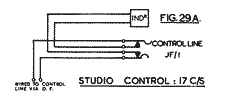
(2) Control Lines for Local Centres Available for Both P.B.X. and Engineering.
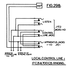
(3) Control Lines using PBX Trunk Circuits.
(4) Control Lines for Extension to Control Position Bays.
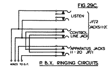
These circuits are provided to enable transmission control positions to maintain communication with centres with which they are dealing. Since these circuits are invariably used for extension purposes, no indicators are provided on the bay. The circuits are wired to lines 11-20 on the line jackfield of the JF/2. This arrangement provides listening facilities across any circuit extended to a control position. The associated apparatus jack will be available for use as a miscellaneous tie line, since the wiring between the inners of the line and apparatus jacks has been removed.
The circuit arrangement is similar to that shown in Fig.29C except that the wiring shown between the inners of apparatus and line jacks is removed.
In the larger Control Rooms two of these bays are installed, one being associated with main S.B. Circuits and the other with studio control circuits. The extension control lines to transmission control positions may be divided over two bays, or wired via listen, line and apparatus jacks on one bay to terminate on the second bay. All wiring on this bay is carried out in multi-core cable. Space is available for a miscellaneous jackfield if one is required.
Multi-Distribution Bay (Fig.30) (Ring Main).

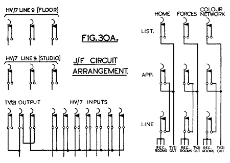
The function of the Ring Main Distribution Bay is to distribute the main programme networks with which a particular centre is concerned, to the studio, recording rooms and other specified listening points within the building. Each listening point is supplied with a multi-point Switch Unit, Type HV/7, which makes it possible for individual listening points to select any of the main programmes for housephone or loudspeaker listening. The HV/7 unit accommodates 9 lines, lines 1-7 being allocated to definite programme networks. The 8-strip jackfield is used for normalling the output of the TV/21 amplifiers to the HV/7 lines 1-7. Line 8 of the HV/7 unit is, in the case of studios, normally wired to the output of the OBA/8 associated with each studio.
Line 9 of the HV/7 unit is terminated on the third jack-strip from the top in the case of floor distribution to offices, etc., and to the fourth jackstrip in the case of studios. This arrangement provides facilities for feeding any floor or any studio with a special programme selected in Control Room.
Distribution of recording room programme sources is effected on the JF/2 below the main jackfield. In this case arrangements are made for feeding all the recording rooms in the building with each of the main programme networks. A typical arrangement of the jackfields is shown in Fig.30. There will, of course, be considerable variations of this arrangement with individual studio centres and, although the foregoing information conveys a general idea of the ring mains distribution scheme, it is not possible in this Instruction to give details of the specific conditions obtaining at each of the different centres.
Miscellaneous Test Apparatus Bay (Figs.31, 31A).

This Bay is not normally fully equipped but provides space for miscellaneous testing equipment. The actual equipment will depend upon the requirements of the Station and the availability of apparatus. Space is allocated on the bay for the following apparatus:
(1) CALIBRATING UNIT, CAL/1.
This unit is designed to provide a standard voltage for calibrating a programme meter or amplifier detector.
(2) DC TEST METER and associated switching, designed for measurement of line loops and insulation.
(3) TEST PEAK PROGRAMME METER AMPLIFIER, TPM/3 AND MAINS UNIT MU/16
This Unit provides facilities for the measurement of programme volume, or tone level , where such volume or level lies between the values of +10 and -50db.
(4) WHEATSTONE BRIDGE.
The Wheatstone Bridge is provided for the measurement of resistance on lines , etc.
(5) JACKFIELD JF/2.
The Jackfield JF/2 is used for terminating the apparatus listed above and for the provision of tie lines to other bays. There are also a number of miscellaneous test jacks. The layout of the bay and jackfield is shown in Figs.31 and 31a.

AC Test Apparatus Bay (Figs.32, 32A).

(1) 1,100c/s OSCILLATOR OS/9 WITH MAINS UNIT MU/16.
This is a fixed frequency oscillator, having a stabilised output of zero dB at a frequency of 1,100 c/s.
(2) VARIABLE ATTENUATOR AT/19.
This is a 600 ohm balanced attenuator, having attenuation values from zero to 55db. And capable of adjustment in steps of .5db.
(3) TONE SOURCE TS/7 WITH MAINS UNIT.
This is a Beat Frequency variable oscillator, having a range from 40-15,000 c/s. Its output impedance is 600 ohms and its output level variable between +20 and -50db. In steps of 10db. In exceptional cases provision may be made for a maximum output level of +26db., but this is not normally available.
(4) AMPLIFIER DETECTOR AD/4 WITH MAINS UNIT MU/16.
This measuring instrument has an input impedance of 600 ohms or 30,000 ohms and is suitable for the measurement of levels between +10 and -55db. Measurement can be obtained to an accuracy of 0.1db.
(5) JACKFIELD JF/4.
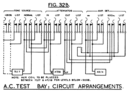
This jackfield, comprising 4 separate strips, Type JF/1A, provides terminations for the above apparatus and other inter-bay lines, miscellaneous test jacks, etc. The layout of the bay is shown in Fig.32 and the wiring of the apparatus to the jackfield in Fig.32B.

