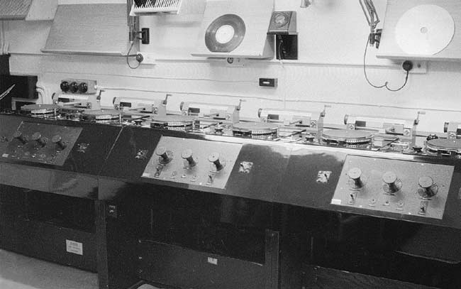
A bank of TD/7s in S3, 1962. The small black box on the wall, just right of centre, carried a jack with a feed of 900Hz tone. This could be compared with the tone recorded on the discs to check that the turntable was running at the correct speed. The centre fader of each set of three was intended for use as a cubicle mic fader.
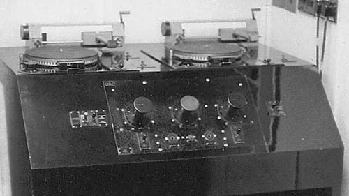
There were two ways of setting up a disc. First, the lever and drum method. The pick-up was lowered onto a revolving disc, and lifted with the lever on the right as soon as the required start point was found. The drum, on the left, was then turned to move the arm back a bit. The drum was calibrated to move the P/U back one groove per division on direct cut discs with 104 grooves per inch which was the standard used on Presto and BBC Type D disc cutters. To play the disc the pick-up was again lowered onto the turning disc.
The second method was the drop start. This was operated by a lever (or button on earlier models) which lowered three rubber pads which held the disc above the turntable and thus dropped the disc onto the moving turntable. Setting up was fiddly - remember that it wasn't possible to wind back the disc. To play from the start, the record was positioned with the label upright and the stylus placed in the 'first' groove. The disc was then started and the number of revolutions counted until programme was heard. It was then stopped, reset so that the label was upright again, the stylus replaced in the first groove and the disc played, once again counting revolutions. Half a rev short of the previous count the disc was stopped, ready to be played on cue.
The following is part of a Technical Instruction issued in May 1946.
Twin-turntable disc reproducing desks for 78 r.p.m. discs only, originally known as TD/7 desks, have been in general use for a number of years with various modifications made to meet specific needs. Each desk comprises two turn-tables driven by induction motors, the drive being controlled by a worm-driven governor, fitted with a speed- adjusting lever. Each turn-table has a stroboscopic speed indicator consisting of either a number of holes round the edge of the turn-table, behind which is a neon lamp fed from the 50 c/s mains supply, or a number of alternate black and white.
The disc-reproducing head associated with each turn-table is mounted on a counterbalanced parallel-tracking arm which is provided with a raise-lower lever and a groove-locating device, details of which are given under the next heading.
Each desk contains a pre-fade-listening amplifier, which, with associated switching arrangements, permits checking or setting up of the disc on one turn-table whilst the other is being used for reproduction to line. A microphone circuit, incorporated with each desk, provides facilities for linking commentary during gramophone recitals.
At centres where facilities are required for reproducing multi-disc programmes, a bank of six turn-tables is provided by three TD/7 desks installed adjacent to each other, the common output being taken to local studio or control room amplifying and switching equipment.
Groove-locating Unit GLU/3.
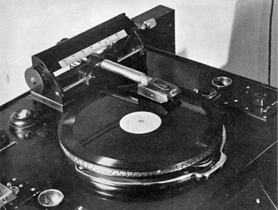
The units incorporate a cam-operated raise-lower lever, and a vernier adjustment which enables the needle to be lowered into any desired groove. The tracking arm is fitted with a movable counter-weight which can be slid along the arm extension to give correct pressure of the needle point upon the disc.
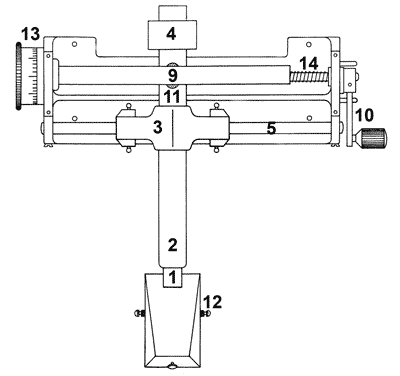
The tube passes through the sliding carriage (3) and is extended to the back of the assembly. A sliding counter-weight (4) is fitted over the back of the tube and small movements of the weight along the tube alter the pressure of the needle point upon the disc. This is normally adjusted to produce a pressure of 2 ± Ľoz. When correctly adjusted, the counter-weight is fixed in position by a grub screw.
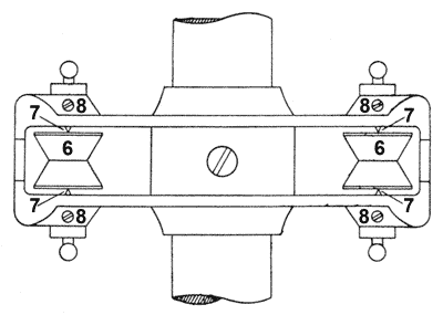
The reproducing head is lowered and raised by operating a cam bar (9) by means of the lever (10). When this lever is raised, the cam bar makes contact with a rubber insert (11) fixed on the back of the tracking arm, thus depressing the back of the arm and raising the needle from the disc. The purpose of the rubber insert is to prevent the head sliding about when in the raised position and to ensure that, when the arm is subsequently lowered, the needle falls into the groove which it was previously tracking.
Where it is necessary for the needle to be lowered into a specified groove, the carriage may be moved by adjusting the vernier control (13) with the tracking arm resting on the cam bar. A circular channel is cut inside the vernier knob and the end of the cam bar, which is reduced to Ľ inch diameter, neatly fits into this channel and is held there by the spiral spring (14). The depth of the channel varies from zero to the full depth of the knob, so that as the knob is turned, the cam bar is moved in one direction or the other, depending upon the direction in which the knob is turned. A scale, engraved on the outer surface of the knob, is calibrated so that one division corresponds to a movement
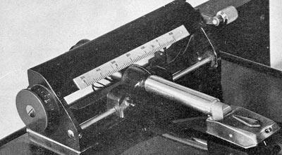
A coarse scale is fixed on the front edge of the plate which covers the top of the unit. This scale is divided into inches and tenths, the white line on the top of the carriage acting as a marker.

