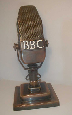
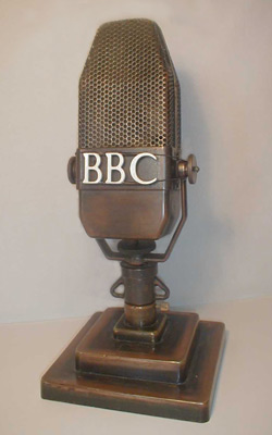
Almost a BBC trademark and still instantly recognisable as a BBC microphone even without the logo attached. Today some national newspaper cartoonists still draw an AXBT shaped microphone if the subject of their cartoon is a radio studio.
In May 1931 RCA demonstrated their ribbon mic in Hollywood and it came to the BBC's notice. Unfortunately the price, including the head amplifier, was £130 which in today's terms is around £5200. As this was not affordable, the BBC set about designing its own version, which was introduced in 1934-1935 as the Type A microphone. There was some concern about the possibility of patent infringement but eventually it was decided that the BBC had a valid patent. The mic was manufactured for the BBC by Marconi for £9 each, about £360 today.
The original aluminium ribbon had objectionable resonances and was replaced with very thin aluminium foil and the modified mic was called Type AX. Another problem was found when the mic was used near an electromagnetic field; this was solved by arranging the internal wiring of the mic so that induced noise currents cancelled out and thus the Type AXB was born in 1943.
The final modification was to use Ticonal magnets in place of the original cobalt steel magnets. This gave 6dB increased sensitivity and the letter T was added to the code number. Weighing in at just under 9¼ lbs., type AXBT appeared circa 1944, and is illustrated here.
The following Technical Instruction from 1936 describes in detail the original Type A microphone and, in the second part, discusses balancing techniques using the mic.
PART 1. TECHNICAL DESCRIPTION.
A brief summary of earlier experimental developments which led up to the Type A microphone
Description
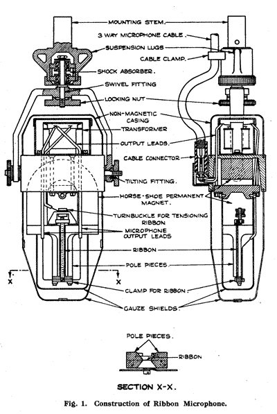
The microphone consists essentially of a thin corrugated ribbon of "hard aluminium" approximately 2½" long ¼" wide and .0002" thick suspended in the gap formed by the specially shaped soft steel pole pieces of a large cobalt steel permanent magnet. The field in the gap is parallel to the surface of the strip and at right-angles to its length and is sensibly uniform. The ribbon is held at either end in non-magnetic supports and is only lightly tensioned. Its natural frequency occurs in the region of 20 c/s and the movement is heavily damped by the magnetic field, which is of the order of 1,600 gauss. Movement of the ribbon in response to the sound, in a direction normal to its face, gives rise to current along its length. The resistance of the ribbon is only about 0.15 ohm and a mu-metal transformer, forming part of the microphone assembly, is provided in order to step-up the output impedance to approximately 300 ohms.
Two silk lined non-magnetic gauze shields are fitted, one enclosing the ribbon assembly and the other, outside it, enclosing the complete magnet assembly. These protect the movement from dust and also from air currents which might give rise to heavy L.F. surges. The upper part of the microphone unit, containing the output transformer screened in a mu-metal box, is enclosed in a non-magnetic sheet metal casing.
The microphone is carried in a gimbal mounting fitted with a shock absorbing attachment provided both with suspension lugs and with an adaptor that fits into any of the standard telescopic studio stands in place of the usual ring adaptor. It can thus either be mounted on such a stand with the ribbon on the top, or suspended by means of the shock absorbing thongs provided, with the ribbon at the bottom. Provision is made for inclining the microphone with respect to either the vertical axis or to the horizontal axis, and for locking it in position when suitably set.
The connections to the microphone are made by means of a standard two-conductor shielded cable, via a special 3-pin adaptor. The output pins are closely spaced, and are connected to the secondary of the transformer. The earth pin is the one displaced slightly to the right and it is connected to the casing of the microphone. The earthed shield should be connected via the adaptor to this pin. The primary of the transformer is connected directly to the two ends of the ribbon, the connection to its outer end being duplicated in order to reduce the resistance in the circuit.
The output level from the microphone itself is -74 db., zero level being one volt output for a pressure wave of one dyne per square centimetre. This is 4 db. below that of the S.T. & C. moving-coil microphone with its associated 3/1 step-up transformer.
Operation
The action of the microphone is not the same over the whole of the frequency band. Up to about 4,500 c/s it operates as a "velocity" microphone, above this frequency and up to about 9,000 c/s it operates as a "pressure" microphone, while above 9,000 c/s it functions on the "velocity" principle again.
Over the lower part of the frequency band the sound wave exerts pressure on both sides of the ribbon, reaching the back by diffraction round the pole pieces. The pressure on the back is slightly out of phase with that on the front, due to the difference in length between the paths travelled by the sound wave from the source, and the response of the microphone is proportional, not to the actual pressure of the sound, but to the resultant of the pressure exerted on both sides of the ribbon. This is actually proportional to the pressure gradient of the sound wave, which is mathematically identical with the particle velocity of the sound, whence the description "velocity" microphone. Since the particle velocity increases with frequency, it might be expected that the response of the microphone would show the same tendency, but this is counteracted by a tendency, due to the mass of the ribbon, for the response to fall as the frequency increases. In practice the response of the microphone is substantially uniform over the part of the frequency band under consideration. When, however, the path difference exceeds one half of the wavelength of the incident sound wave, the velocity principle breaks down and the efficiency falls rapidly. The frequency at which this fall in the frequency characteristic commences is determined by the cross-sectional dimension of the pole pieces which fixes the difference between the length of the paths from the source of the sound to the front and back of the ribbon respectively.
In this model this critical frequency occurs at about 4,500 c/s, but the drop in the frequency response above the critical point is effectively counteracted by shaping the pole pieces to provide a resonant cavity on each side of the ribbon. These cavities are broadly resonant over a large part of the range from 4,000 to,9,000 c/s. Over this range of frequencies, therefore, the microphone behaves as if it were a double-sided pressure microphone mounted in a small baffle. At frequencies above 9,000 c/s, the velocity principle again comes into play, since the high frequency sound waves are able to pass between the small air gap between the pole pieces and the ribbon, producing a pressure difference between front and back, and, in theory, a new half wave condition at about 20,000 c/s. (The R.C.A. ribbon microphone is a pure velocity microphone in which, as the result of special design of the pole pieces, the critical frequency occurs at about 9,000 c/s. However, the microphone is considerably less sensitive than the B.B.C. ribbon microphone and its high frequency response (above 2,000 c/s) is not so good.)
The combination of the velocity and pressure effects described, gives an extremely good frequency characteristic which is uniform to ±½ db. between 100 c/s and 6,000 c/s, -2 db. at 7,000 to 8,000 c/s and -3 db. at 9,000 c/s, the present limit of accurate measurement. There is however good reason to believe that the frequency response is well maintained up to at least 16,000 c/s. Below 100 c/s there is a rise in response with decreasing frequency, with a maximum at 20 c/s, amounting to +4 db. at 50 c/s. Correction for this, and for the slight loss above 7,000 c/s is applied in the "A" amplifier.
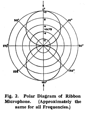
The response of the human ear is directly proportional to the sound pressure and is a function of distance only, but the complete mathematical expression for the response of a velocity microphone includes a term involving also a function of the distance of the sound source and its frequency. Fortunately, this term is negligible for all normal distances, but if the sound source is very close to the microphone the effect is to increase greatly the low frequency response.
The particular importance of the above unique features will be discussed in Part 2.
Microphone Circuit
Related page
It should be remembered that at the time of this
TI BBC practice placed the first stage of amplification in the main control
room which could be at a considerable distance from the studio. The mixers
in studios were passive devices.
See the description of technical aspects of Broadcasting House in 1932 here.
See the description of technical aspects of Broadcasting House in 1932 here.
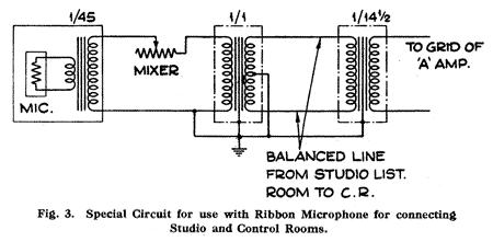
Certain changes have been made in the circuit of the "A" amplifier for use with ribbon microphones, in order to screen the amplifier completely from the input line, and to modify the frequency characteristic of the amplifier so that in conjunction with the ribbon microphone the desired overall frequency response is obtained.
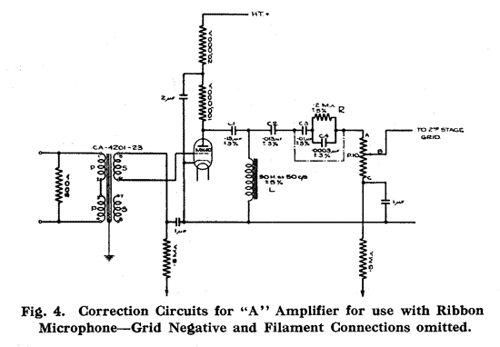
By leaving the secondary of the input transformer unloaded a gradually rising characteristic is obtained, the rise amounting to about +3 db. at 9,000 c/s and thus compensating for the slight fall at the upper frequencies in the frequency response characteristic of the microphone itself. The increase in the low frequency response of the microphone is corrected by the network consisting of the condensers C1 and C2 and the inductance "L," connected in the output of the first valve and giving a fairly sharp cut off in the region of 50 c/s. A similar result can be obtained by reducing the value of the coupling condenser in the output stage of the amplifier, which is the scheme adopted for modifying existing amplifiers. Actually as shown in Figure 5, an additional small condenser C5 is connected in series with the existing condenser. By these means a sensibly flat overall frequency response characteristic is obtained for the "A" amplifier and ribbon microphone from about 50 c/s to about 10,000 c/s.
At the present time it is considered desirable somewhat to over-emphasize the upper frequencies in the transmission in order to compensate for the prevalent deficiency in response of the average listener's receiver and loudspeaker at these frequencies, and it has been found in practice that the desirable frequency characteristic is one gradually rising above 1,000 c/s to about +6 db. at 8,000 c/s. Arrangements will ultimately be made for this to be effected by the use of an equaliser in the input to the radio transmitter and up to this point each part of the transmission chain will be designed to have a uniform frequency response characteristic.
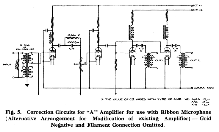
As a temporary measure, however, the rising characteristic desired is being obtained in the "A" amplifier. This is done by the introduction in the output of the first stage of an additional network (see Figures 4 and 5), consisting of condensers C3 and C4 the latter shunted by the resistance R. Where the arrangement of Figure 4 is adopted the condensers C2 and C3 may be combined into a single condenser of equivalent capacity.
Maintenance
From a maintenance point of view the microphone is extremely reliable and is entirely unaffected by normal atmospheric changes in temperature and humidity. It is very robust and if always handled with reasonable care the only faults liable to develop are that the ribbon may in time become slack, and that small particles of iron may collect in the gap and impede the free motion of the ribbon. Provided the shields are not disturbed, trouble due to the latter cause is very unlikely, while as regards the former, provision is made for retensioning the ribbon. If, however, the performance of a microphone is suspected for any reason, it should be returned to the Equipment Engineer for attention. In the ordinary course, therefore, it should be unnecessary to remove either of the protecting gauze covers. In the event, however, of this becoming necessary it should be done, not in the workshop but in a room completely free from iron filings or magnetic dust.
In regard to maintenance of the associated microphone circuits, if hum, clicks or any other interference is experienced, attention should be paid to the balance of the lines to earth.
PART TWO. STUDIO BALANCE TECHNIQUE
BALANCE TECHNIQUE FOR STUDIO BROADCASTS
Introduction

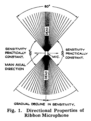
In an enclosed space such as a studio, sound reaches the microphone both directly by the shortest path between it and the sound source and also indirectly after reflection from the walls, ceiling and floor. Such reflected sound is called 'reverberation' and reaches the microphone from all angles. Its intensity depends upon the 'reverberation time' of the studio, which is a property largely determined by the acoustic treatment of the reflecting surfaces. Where the treatment is not very absorbent the reverberation time will be long, that is to say, the studio will be 'lively' and the sound intensity due to reverberation will be high at all points in the studio. On the other hand, if the treatment of the reflecting surfaces is highly absorbent the reverberation time will be short, which means that the studio will be 'dead' and the sound intensity due to reverberation small.
If the microphone in any studio is moved away from the source of the sound, the intensity of the sound reaching the microphone by the direct path will be reduced and therefore the intensity of the reverberation will be proportionately increased. The various types of microphone hitherto available all have marked directional properties at the upper frequencies but not at the low frequencies, with the result that if these microphones are placed at more than a certain distance from the source of the sound, depending upon the acoustics of the particular studio, a hollow low-pitched quality is obtained. This limitation does not apply in the case of the ribbon microphone because it is equally directional over the whole band of frequencies and, therefore, the quality is independent of the direction from which the sound is received.
Apart, however, from the question of the faithfulness of the response of the microphone, there has also to be taken into consideration the fact that the reflected sound reaches the microphone slightly after the direct sound because it has travelled further, the various paths taken by the reflected sound in reaching the microphone being considerably longer than the direct path, particularly so in the case of any part of it which is subjected to successive reflections from a number of surfaces. A certain amount of reflected sound or reverberation is inevitable in all auditoria and is not only unobjectionable but is actually to be desired. Obviously, though, if the reverberation is excessive it will mar the whole character of music and seriously impair diction. This is, therefore, one of the factors which determines in any studio the maximum distance from the performers at which the microphone can be placed. The limitation formerly experienced due to this cause is, however, largely overcome with the ribbon microphone by virtue of its directional property, for as the result of the peculiar shape of the sensitivity curve the amount of reverberation picked up by the ribbon microphone is only one third of that picked up in the same circumstances by microphones of other types. In practice this means that for the same ratio of indirect to direct sound, the ribbon microphone can be placed just twice as far away from the performers as a microphone of any of the types formerly available.
General Principles
Enough has been said to show why, especially in the case of studio broadcasts, the reproduction with the ribbon microphone is more natural than with any other type, and why where the acoustics of the studio are suitable a much more 'distant' balance technique can be employed with it.
Although improved results are in general obtained simply by substituting a ribbon microphone for one of the Reisz or moving-coil type, obviously the best results can only be obtained by using a technique that takes into account the unique properties of the ribbon microphone. In Broadcasting House, where these microphones have been in use for some time, considerable experience in many types of studios has been gained and a special balance technique has been evolved. There are, however, so many variables concerned that it is impossible to lay down rigid rules or, for example, to specify definite distances. A technique suited to one studio may be quite unsuitable for some other studio.
The purpose of this instruction is rather to lay down broad general principles which can be altered in detail to suit local conditions in individual cases. The subject will be treated in this way under separate headings for each of the branches of the programme activities, namely, Music, Productions and Variety, Drama, and Talks. But before proceeding to the special applications attention must first be drawn to certain important rules of general interest underlying all ribbon microphone technique.
Studio broadcasts can, in general, be divided into two classes, namely, (1) those which are internally balanced for a listener in the actual studio, and (2) those which are balanced specially for the microphone and are more or less unbalanced for a listener in the studio.
Speaking generally, the best artistic results are obtained when the internal balance in the studio is as good as possible, and balance trickery or faking is kept to a minimum. The only circumstances in which the 'internally unbalanced' technique is really justified is where the acoustics of the particular studio definitely do not permit of the effect desired being obtained otherwise.
It can be definitely stated that in normal studios one microphone invariably gives much superior technical quality to that obtained when using two or more microphones simultaneously. In general, therefore, efforts should always be directed towards getting the best balance possible on one microphone. If, at the first attempt, there are deficiencies, other layouts should be tried and the use of a second microphone should always be regarded as a last expedient.
If it is necessary to adopt a 'close' technique, perhaps due to the number of performers being too large for the size of the studio, or to an intimate effect being desired as, for example, in the case of a dance band, advantage should always be taken of the double-sided property of the microphone.
The recommendation regarding the advisability of using only one microphone does not condemn the practice of making a change-over from one microphone to another in a different position, when a different effect is desired. On the contrary the practice is definitely encouraged as a natural development of single microphone technique.
For reasons other than technical ones, particularly in the case of production shows, the artistic balance resulting from the use of only one microphone may not be satisfactory. In such cases the simultaneous use of two microphones, or even in rare cases of more than two microphones, is inevitable and the precautions necessary in order to prevent the practice from impairing the quality unduly are explained below.
The ribbon microphone responds to the velocity component of the sound waves and not to the pressure, whereas the human ear is pressure-operated. The absolute magnitudes of the velocity and the pressure are strictly proportional to one another except for low frequencies close to the sound source. When very near the source, therefore, the ribbon microphone may be said to hear the low notes differently from the ear and in practice this difference becomes apparent in an exaggeration of the lower frequencies which imparts a 'boomy' quality to the reproduction. The effect is most pronounced with male speakers. The microphone should, therefore, not be used at a distance of less than two feet and certainly never less than eighteen inches.
Another point that cannot be too strongly emphasised is that whatever the circumstances acoustic screens should never be used close to the microphone. This applies equally to a screen with its absorbent surface turned towards the microphone as to one with its reflecting surface so turned. The practice is objectionable because the screen causes a standing wave pattern to be formed with the result that certain notes are accentuated at the expense of certain others which are diminished. Therefore, even though an absorbent screen close to the microphone may secure a reduction of bass 'boom' it also gives rise to very considerable frequency distortion. For the same reason the ribbon microphone must never be used near a wall. Generally speaking the best position for the microphone in any studio is at a distance from the back wall of about one third of the length of the studio along which the microphone is directed.
Music
Most performances of a musical nature belong (or should belong) to the internally balanced class in which the balance is correct for a listener in the actual studio. For these, the technique is very simple. The individual performers are arranged in a normal concert-hall fashion, and the microphone placed a considerable distance away so that the distances of the various instruments from the microphone do not vary too widely. This technique should always be applied provided the studio acoustics are good, and the players do not occupy more than approximately half the floor space.
It is perhaps best exemplified in the present practice for the Symphony Orchestra broadcasts from the Queen's Hall. For these only one ribbon microphone is used and is placed about 30 feet from the nearest instrument in the orchestra. The resulting broadcast balance is then found to be the same as that for a listener in the hall itself, so that the conductor need not be requested to alter his normal concert hall balance to suit the microphone. For vocalists singing with orchestra, a change-over is made to a microphone only about 20 feet away in order to preserve diction.
Often with a small orchestra the numerical weakness of stringed instruments is compensated for by bringing these nearer the microphone, so as to enable the heavier instruments (brass etc.) to play with the same volume as in a much larger orchestra. This is fundamentally wrong. A really satisfactory result can only be obtained when the principle of internal balance is realised. Conductors should be encouraged to get their orchestras correctly balanced for studio listening, just as they would do as a matter of course if the orchestra were playing to an audience in a concert hall. This applies particularly to the orchestral accompaniment of solo artists. Usually an accompanying orchestra plays too loudly, and the soloist has, therefore, to be brought closer to the microphone, which results in thin orchestral quality, lacking body. In passing, it may be observed that musicians generally seem not to realise the superior beauty of quiet as compared with loud orchestral playing when reproduced on loudspeakers working at average levels.
A few points of detail are worthy of special notice. Stringed instruments for best reproduction should bow across the microphone, not towards it. Also, except for distant strings, a low microphone position, say, five feet or so above the floor, gives better string tone than a high one, especially if in the latter case the microphone is tipped down so as to face nearly horizontal. Pianos, even in accompanying, should always be used open, more or less, and the microphone placed as shown in Figure 2, not too close but 'looking' into the opening provided by the raised lid.
A typical balance for a small musical combination is shown in Figure 3.
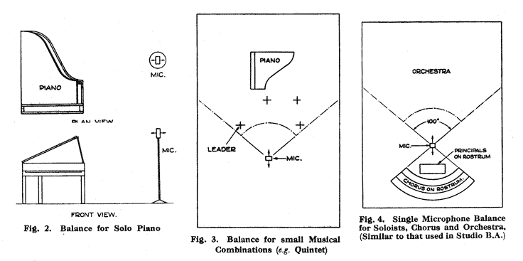
For performances with choir or chorus and orchestra, the best results, especially in regard to diction, are obtained by using both sides of the microphone, the orchestra on one side, and the chorus built up on rostra on the other side . A typical arrangement of this kind is shown in Figure 4. The front row of singers should be at least 2 feet above floor level, so that the microphone may be placed sufficiently high to obtain good orchestral quality.
In a small number of cases, even in broadcasts of a purely musical nature, it may not be possible to obtain the desired artistic effect with only one microphone, and in these cases a double-microphone technique, similar to that described in the next section, should be adopted.
Productions and Variety
A single microphone technique similar to that described above for musical broadcasts may be applied to most (or at least to many) production and variety shows. The main obstacle to adopting this technically superior method of balance on all occasions is the fact that the artists employed in these productions often possess weak voices. Consequently, when the single microphone technique is employed, they have to work close to the microphone and this makes it necessary for the artist's position to be very accurately maintained since a movement forward or backward of several inches will make quite an appreciable difference to the resulting balance with the orchestra. On the other hand, where separate microphones are used for the soloist and the orchestra, the balance is more
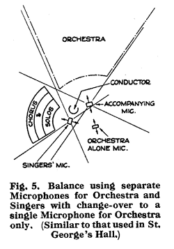
In using more than one microphone simultaneously the important thing to watch is that no instrument or singer is picked up directly by more than one microphone.
For a group of soloists and chorus with accompanying orchestra the solo microphone should have a 'dead' side towards the orchestra, and similarly the orchestra microphone should have a dead side towards the singers. The microphones should be placed as far apart as possible, consistent with the conductor's convenience. It is advantageous to have the orchestra microphone for accompanying purposes quite near to the orchestra, but for orchestral interludes, when the solo microphone is not required, another orchestra microphone placed at a greater distance should be provided and a complete change-over made to it. This technique is illustrated in Figure 5.
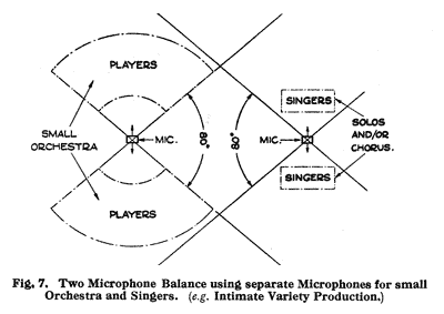
Dance bands should always utilise both sides of the microphone in order to obtain the required intimate effect, and in most cases one microphone should be sufficient. If, however, after careful balancing, one instrument, for example, a piano, is found to be weak, then another microphone, faded only half up and with a dead side towards the main band, may be introduced quite near to the particular instrument.
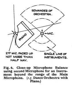
For the balancing of dialogue occurring in productions the technique is similar to that for Drama.
Drama
The convenience of the double-sided property of the ribbon microphone in drama need not be stressed.
The directional property of the microphone is also useful for obtaining distant effects, the artist moving round towards the dead side as well as adopting the more usual expedient of going further away from the microphone. To obtain certain effects it is sometimes necessary for him when at the maximum distance also to turn away from the microphone when speaking.
Attention is drawn to the recommendation against the use of acoustic screens close to the microphone which has previously been given.
Talks
In talks speakers must not be closer to the microphone than 2 feet, and in small studios not further from it than 3 feet. In debates or discussions both sides of the microphone should be used with the speakers facing each other. For the most natural reproduction, speakers should not talk too quietly or intimately, except when this kind of effect is specially desired. As a general rule a natural voice should be used, as if the speaker were addressing several people in an average living-room. In the case of talks for schools, however, the reproduction in the average schoolroom is more natural if the voice is raised slightly.
In 1944 a further TI was produced describing developments of the Type A design, finally resulting in the AXBT.
MODIFICATIONS TO BBC-MARCONI TYPE A RIBBON MICROPHONE
SECTION A. INTRODUCTION.

(1) Improvement in frequency and transient response, effected by changing the springy duralumin ribbon for one of much thinner beaten aluminium foil.
(2) Removal of the characteristic ring, sometimes associated with speech transmission from a type A microphone, by damping the mechanical resonance of the outer transformer casing.
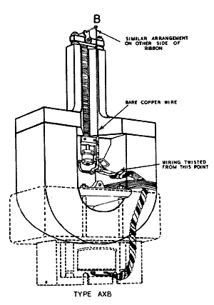
(3) Reduction in interference from magnetic fields, effected by the re-arrangement of wiring between ribbon and transformer in the form of a balanced loop, or more precisely, two balanced loops.
(4) Employment of improved magnetic system.The microphone modified as indicated under heading (1) is designated AX (X denoting the foil used for the new ribbon) and the one modified for balanced wiring as indicated in (3) is designated AB. In the general case both modifications are made simultaneously and the microphone labelled AXB. When the new magnets are fitted the designation becomes AXBT.
Frequency Response.
The tests carried out on the Type A ribbon microphone previous to its introduction into general service were taken under somewhat restricted conditions, the measurements being made at a number of selected points in the frequency range. From these measurements the microphone appeared to have a sensibly linear response over the useful part of the audio-frequency range. After the microphones had been put into general service, it was suspected that at the lower part of the frequency scale resonances were occurring at points intermediate to those at which the original tests were taken and subsequent investigations proved these suspicions to be correct.
Early in 1939, it became necessary to explore the possibility of fresh sources of supply of suitable ribbon material and in the course of this research samples of beaten aluminium foil were obtained the thicknesses of which were considerably less than that of the duralumin ribbon already in general use.
While experiments on different ribbons were proceeding it was observed that response curves, when using the beaten aluminium foil ribbons, differed considerably at the lower frequencies from those obtained with the original duralumin ribbons.
After numerous comparative tests, it was found that, whereas the curve of the original ribbon had pronounced resonances up to about 500 c/s, mainly resulting from modes which were roughly odd multiples of the fundamental resonance, the curve for the beaten foil ribbon over the same frequency band was sensibly smooth. This difference was partly due to the fact that the normal resonance modes of the beaten foil were very much lower in frequency than those of the original ribbon and partly to the decrease in springiness, which causes increase in damping.
Transient Response
With the Type A microphone, the ribbon material was standardised to produce a fundamental resonant frequency of 35 c/s, because many of the ribbons produced from the selected material could not be made to resonate below this frequency. In this case the maximum departure from a smooth curve amounted to only ± 2.5 db. above 50 c/s, which would at first sight appear to be reasonable. Investigation proved, however, that in the neighbourhood of each resonant mode, the slope of the frequency response curve was very steep. This condition implied a low degree of damping which would naturally lead to defective reproduction of transients, a state of affairs which was confirmed by direct measurements of transient response in which the ribbon was excited electrically. On the other hand, similar tests applied to the X-foil microphones indicated that the ribbon movement was substantially aperiodic.
As previously explained, this improved response was due to the lower frequency of the fundamental resonance and the increased damping resulting from the nature of the ribbon material.
As a result of the above experiments, it was decided to review the whole question of ribbon design. The following notes summarise the principles governing the re-design of a ribbon for a given magnetic system.
Choice of Ribbon Material.
It has long been established that the air loading on the moving element of a velocity microphone is an almost pure mass reactance and that to obtain maximum efficiency the ribbon mass should equal the equivalent air mass. The air mass is, of course, determined by the geometrical shape of the pole-pieces which, in the case under consideration, was already determined. It was found by experiment that the optimum mass for the ribbon was equivalent to 0.6 mg/sq. cm. which, in the case of aluminium, corresponds to a ribbon thickness of .00009 inch.
It can be demonstrated that for a ribbon of given length and width but with the thickness varied according to the material so as to keep the mass constant, the maximum output voltage obtainable across a given load (assuming a proper matching transformer to be provided in each case) is proportional to 1/√(rd) where r and d represent the resistivity and density of the material respectively. This factor, when worked out for all practicable materials, is found to be the greatest for pure aluminium and slightly less for duralumin.
Modes of Resonance.
A microphone ribbon has two sets of resonance modes, one set being due to the motion normal to the plane of the ribbon and known as the normal modes and another set associated with side to side motion, called the transverse modes.
Any slight twist of the ribbon, which can hardly be avoided in practice, will introduce coupling between the two types of mode so that, assuming that the normal resonance may be reduced to a minimum, the performance of the microphone is still affected by the transverse resonance modes, the frequencies of which are largely independent of tension but do not, however, increase with ribbon stiffness. The aluminium ribbon, having a thickness of .00009 inch, is by no means free from the effects of transverse resonance modes.
Experiments proved that a ribbon of approximately half this thickness was, however, relatively free from transverse resonance effects and that its efficiency was very little reduced.
The choice of actual ribbon material was of necessity governed to a large extent by supply and it was found that supplies were available of a ribbon having a thickness even less than that indicated above, with a mass of the order of 0.2 mg/sq. cm. The sensitivity of such a ribbon was still as good as that of the original duralumin ribbon, which had a thickness more than twice the optimum.
Form of the X-Foil Ribbon.
The form of the X-foil ribbon is very similar to that of the original ribbon. The ribbon is corrugated transversely, but the corrugations are kept to the minimum required to prevent the ribbon from curling into a U-shape. Deeper corrugations would be undesirable, since they would tend to flatten out after a period of use and cause the ribbon to sag.
Impedance and Line Transformer.
The impedance of the new ribbon (which is substantially a pure resistance) is approximately four times that of the old, thus necessitating the re-design of the line transformer to maintain a 300 ohm output impedance.
Reduction of Mechanical Resonance of Transformer Casing.
The Type A ribbon microphone sometimes produced a characteristic ringing effect during speech transmission, which was found to be due to resonances associated with the transformer casing. As modification of the transformer was necessitated by the change of ribbon, the opportunity was taken to reduce the ringing effect by applying damping material to the casing. This damping material consists of commercial grade plasticine pressed firmly and evenly over the inside of the casing.
General Performance of Type AX Microphone.
The sensitivity of the Type AX microphone is the same as that of the Type A. The rise in low-frequency response as the resonant frequency of the ribbon is approached, which is a feature of the Type A microphone, is absent in the Type AX, since in this case the ribbon resonance has virtually been removed. There is, therefore, no need for low-frequency correction in the microphone amplifier.
It should be noted, however, that all velocity microphones have a rising low-frequency response when operated at very close range and the Type AX is, of course, no exception to this rule.
Over the middle and upper-frequency range the response of the Type AX is identical with that of the Type A microphone.
SECTION C. REDUCTION OF MAGNETIC INTERFERENCE.
Experience has shown that although the Type A microphone is adequately screened against interference from electric fields, it is susceptible to interference
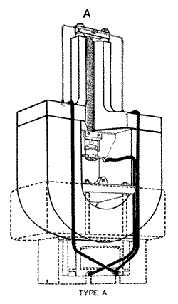
The pick-up was known to be due to the wiring of the low-impedance circuit, i.e. the resultant loop formed by the ribbon and the wire connecting it to the primary of the transformer. It would seem obvious that the interference could be reduced to a minimum by restricting the area of this loop. This method is not very effective, however, because a large part of the interfering field is concentrated by the pole-pieces and some pick-up in the loop is inevitable. An alternative method is the arranging of the wiring so that two loops are formed in such a way that the fields induced in them are in direct opposition, so that their effects cancel each other out.
The arrangement of the loops in the Type A microphone did, in fact, approximate to this condition (Fig. 1a), but because the shape of the pole-pieces prevented the two loops being in precisely the same plane, the cancellation effect was by no means complete. The result was, in fact, worse than that obtainable by a reduction in loop area in the form of a single loop run from the top of the ribbon and keeping it close to the chamfered pole-face.
SECTION D. IMPROVED MAGNET SYSTEM.
Recent experiments have resulted in the improvement of the sensitivity of the ribbon microphone by the employment of a new magnet system. The increase in sensitivity is of the order of 6db.
In the new system, the magnet consists of two separate blocks of Ticonal - a material which is capable of producing a flux density twice as great as that of the cobalt-steel magnets previously used. The reason for using two separate blocks in preference to a horse-shoe system is mainly that it simplifies the process of magnetisation. A horse-shoe magnet of this material can only be efficiently magnetised by the use of an inconveniently large magnetising current. Furthermore, it is possible to obtain greater efficiency by using the separate blocks. The two blocks are mounted on a mild steel base-plate, the dimensions of the complete structure being similar to those of the original magnet system. The only modification to the general assembly is a slight alteration in the methods of clamping the system to the transformer housing and of securing the inner gauze cover.
Some microphones have already been fitted with new magnets and more microphones of this type will become available in the future.
In the general case, where the new magnets are fitted, the modifications referred to in Sections B and C will have been carried out and the designation of such microphones will be ABXT.
SECTION E. MAINTENANCE.
From a maintenance point of view, the microphone is extremely reliable and is entirely unaffected by normal atmospheric changes in temperature and humidity. It is very robust and if always handled with reasonable care the only faults liable to develop are that the ribbon may in time become slack and that small particles of iron may collect in the gap and impede the free motion of the ribbon. Provided the shields are not disturbed, trouble due to the latter cause is very unlikely.
In the ordinary course of events it should be unnecessary to remove either of the gauze covers and it must only be done on the instructions of the engineer in charge of the station. If the covers have to be removed for inspection, the following points should be noted :-
1. In no circumstances should the microphone be opened up in or near a workshop but in a room which is completely free from iron filings or metallic dust. This is of particular importance in the case of the Type AXBT, which has a very high flux density and consequently, a considerably greater attractive force.
Care must also be taken to exclude draughts from the room in which the microphone is being opened up or the ribbon may be irreparably damaged.
2. In the case of microphones having Ticonal magnets very great care must be taken not to touch the magnet with the screwdriver used for releasing the cover-retaining screws.
No iron or steel objects of any kind should be left in the vicinity of the magnet while the cover is off. One reason for this is that if an iron or steel object should touch the Ticonal blocks a consequent pole will be permanently established at the point of contact and the leakage of flux from such a pole will appreciably reduce the efficiency of the magnet. Another reason is the danger of tools or other ferrous objects being accidentally drawn into the gap and so damaging the ribbon. The latter consideration, of course, applies in some measure to all types of ribbon microphones.
3. The greatest care must be taken not to disturb the balanced-loop wiring, for a very slight displacement of this wiring may introduce magnetic pick-up which the balanced loop is designed to counteract.
4. If, when placed in a horizontal plane, the ribbon sags perceptibly from its alignment between the pole-pieces, the microphone is unfit for service and should be returned to Equipment Department. No attempt must be made to correct the tension by adjustment of the sliding clamp.
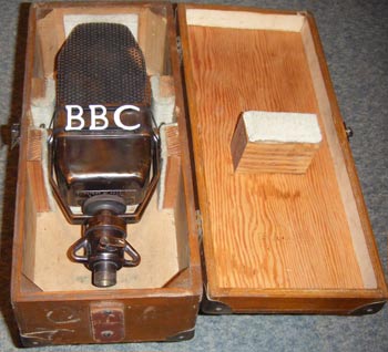
The final photo, from Roger Beardsley, shows an AXB nestling in its wooden box.

