Technical
On this page: The Control Room | Amplifier
Switching | Programme Chain and Amplifiers
Switching and Source Selection | Destination Switching | Control Room Mixers | The Studio
Dramatic Control Panels | Music Control Panels
Switching and Source Selection | Destination Switching | Control Room Mixers | The Studio
Dramatic Control Panels | Music Control Panels
Here we have tried to present a more detailed description of the technical facilities at Broadcasting House in 1932 than we have given on the earlier pages. Our main source of information is "A Technical Description of Broadcasting House" published by the BBC at the time. Some extra details have been gleaned from Edward Pawley's "BBC Engineering 1922-1972" (BBC, 1972), the 1933 BBC Handbook and F. C. Brooker's 1942 Engineering Division Training
It has not been possible to work out how every part of the system operated. In some areas there is a total lack of information, in others we find contradictions. But hopefully we have presented here as accurate a description as is possible today, at least until more detailed contemporary sources can be found.
The Control Room
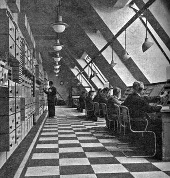
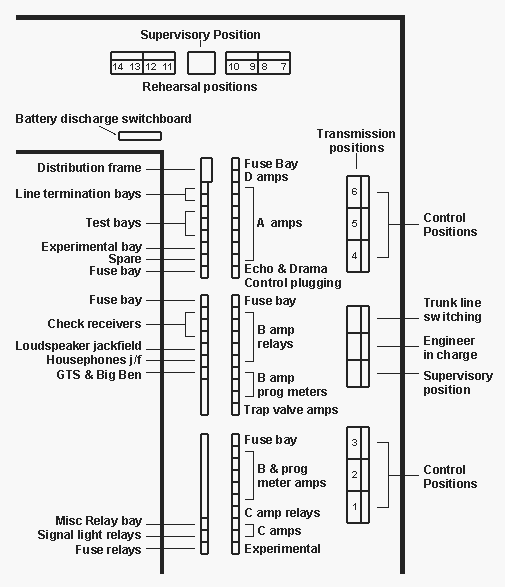
We'll begin with the technical heart of the building - the Control Room. The photo, right, was taken from a position near the bottom of the general layout drawing, below.
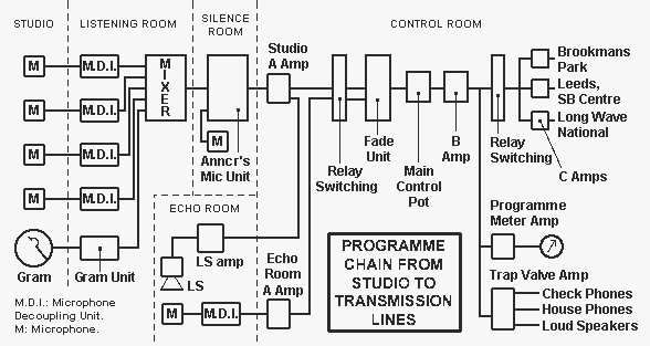
It's important to remember that this really was a 'control' room. Many of the studios had just a single microphone the output of which was wired directly to the control room. In these, and indeed in most other cases, the control of level was entirely done at the control positions in CR. Studios were not equipped with programme meters. Those studios with more than one microphone had a simple passive mixer installed in a 'listening room' which also mixed in the output from gramophones where these were provided. If there was a 'silence' or 'announcing room' then the output from the mixer was fed through the announcer's desk where he could switch (not cross-fade, it seems) between the studio microphone and his microphone for announcements. The output of this desk was then fed to CR, and was there routed through a control position.
There were a further two types of mixer, one for music programmes, the other for drama. These were located remotely from the studios, and allowed the operators to monitor the programme on loud-speakers - not possible in the Control Room, where headphones were the order of the day.
Related page
Apart from the preamplifier built into the condenser microphones and mains-powered loudspeaker amplifiers, the Control Room housed all the amplifiers necessary to the broadcast chain. There seems to have been three main reasons for this:
- The system had been 'tried and tested' at Savoy Hill
- The amplifiers were only switched on when needed as the valves used had a limited life
- All the amplifiers were powered from storage batteries as mains powering wasn't considered reliable.
- 6 volts for the valve heaters
- 300 volts for the high tension (HT) supply
- 3 grid-bias supplies of 2, 12 and 24 volts
- 4 volt filament supply for the 'A' amplifiers only which were indirectly heated to reduce valve noise and to minimise interference caused by switching other amplifiers fed from the same battery.
Amplifier Switching
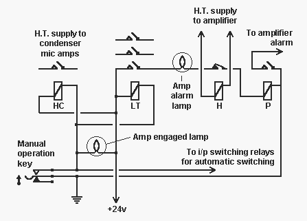
The manual operation key was provided mainly for use when testing amplifiers and probably when setting up sources for the Dramatic Control Rooms. The switching was usually done by the source selection and routing system. 'A' and 'D' amps were automatically switched on when the associated input switching relays were operated from the CR control positions. 'B' amps were switched on by the control positions' first operating key and 'C' amps by a similar key on the simultaneous broadcast position.
There was an alarm system to warn the engineers of an amplifier failure. The H relay would release if the amp's HT feed fell below a certain level, perhaps because of a fuse blowing or a valve failing. This lit an alarm lamp on the bay and operated the P relay. The P relay, in turn, lit another alarm lamp and a bell. The engineers could then find the bay with a lit lamp, and check the relevant amplifier by looking through the valve windows in the amp casing.
The Programme Chain
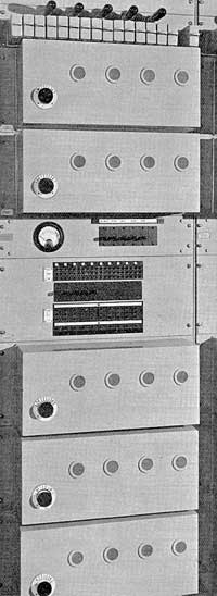
Each 'A' amplifier bay was equipped with five amplifiers, a jack field, relays, alarm lamps and termination strips for connecting the cables from the studios, etc. to the amplifiers. The jackfield provided apparatus, line and listen jacks for the inputs and outputs of the amplifiers.
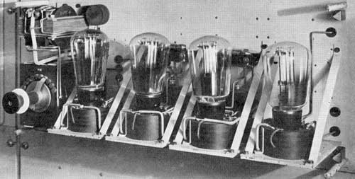
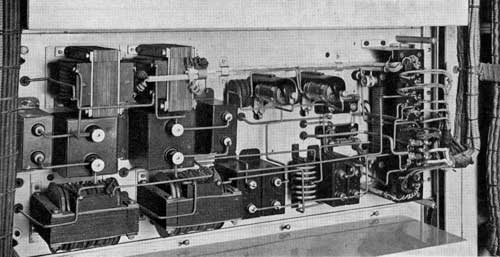
Above left - a view of the front of an 'A' amplifier
with the cover removed. Note the stud potentiometer, which gave gain control
in 4dB steps. Maximum gain was about 50dB.
Left - the back of the 'A' amplifier.
Left - the back of the 'A' amplifier.
Another bay in the same rack as the 'A' amps had jacks accessing a second output of the amps. This was used for echo; the inputs to the echo room loudspeakers also appeared on this bay. The echo room mics were wired to further 'A' amps. the outputs of these were then plugged as required to the source selection system. The same bay contained the jacks for connecting the inputs of the dramatic control panel.
The outputs from the sources' A amplifiers at -18dBu were distributed to the control positions in the control room where the operator (an AME, Assistant Maintenance Engineer) selected a studio on his 2 or 4 channel 'fade unit'. The output of the fade unit then passed through the 'Main Control Potentiometer'.
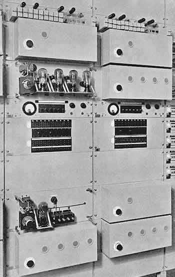
They were mounted on bays together with their associated programme-meter amplifiers. In the photo - right - the 'B' amps are the ones with four inspection windows. The relay switching arrangement included an extra relay to operate the meter amp which was considered as part of the 'B' amplifier circuit. A stud potentiometer controlled gain in 4dB steps, the maximum available being about 40dB.
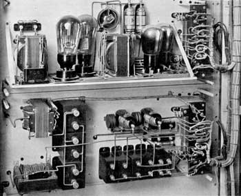
left - The back of a 'B' amplifier and, above it, a programme-meter amplifier. The latter fed a meter with a scale that looked just like a PPM but wasn't. The meters were neither peak reading nor average reading. Line up was to '5' and peaks were to '7'. The PPM did not arrive until 1938 and for a time retained the '5' and '7' line up.
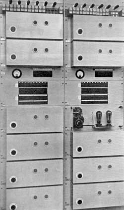
The outputs of the 'B' amplifiers were wired to 'C' amp input switching relays, which were operated from the simultaneous broadcasting position. There were twelve 'C' amps and ten sources - the outputs of the six transmission control positions and four of the 'D' amplifiers. An indicating device informed the SB engineer which source was connected to any of the 'C' amps.
The 'D' amplifiers with a gain of about 45dB were used to amplify incoming Post Office lines and were somewhat similar to 'A' amplifiers. There were 6 of them, 2 for incoming programmes from Leeds and Daventry and the other 4 for Outside Broadcast lines and as spares.
In addition to these 4 types of amplifiers there were also 'trap-valves' which were buffer amplifiers used to feed the studio listening room loudspeakers and for various headphone feeds. Each transmission position had a trap valve amplifier and there were 3 more for rehearsals and spares.
Switching
The system used was known as 'B and C input switching'. It involved switching the various sources to the inputs of the control positions and thus to the input of the 'B' amplifier. The sources available were nineteen studios, the two Dramatic Control Panels, an interval signal, two SB lines, two OB lines, one echo room, Big Ben and two spares.
Every destination, which in 1932 usually meant a transmitter fed by a Post Office line, had its own 'C' amplifier feeding it and the outputs from the control positions were switched to the inputs of the 'C' amplifiers. Various means of performing the switching are possible but in the 1932 control room it was done with relays - around 1,500 of them for the B and C input switching alone.
Source Selection
In the following description note that relays were often made to operate by earthing one side of the relay coil, the other side being connected to 24 volts - in other words a negative earth system. Also amplifiers in the control room were powered by simply switching on the heater volts, there was no current drain from the HT or grid-bias supplies if the heater supply was off.
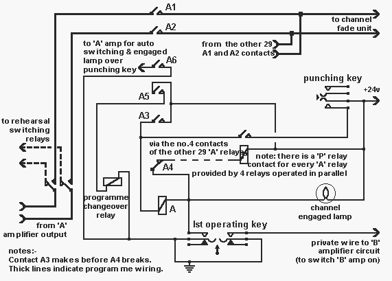
To select a source to a fade unit, the AME first operated a key (the 'first operating key') associated with the channel input that he wished to use on his control position. This did three things; it applied an earth via what was known as a 'private wire' to a relay which turned on the control position 'B' amplifier, it applied an earth to the 'P' relay via the A4 back contacts of the 30 A relays associated with that control position input and it turned on the channel engaged lamp. The P relay operated and provided a path through its contact from the A relay to the 'Punching Key'. There were 30 of these, one for each source, and when one was momentarily pressed, 24 volts was applied via the closed P relay contacts and via the A relay to earth. The A relay operated, contact A3 was arranged to close first and apply 24 volts to hold relay A operated. Contact A4 opened and broke the circuit to the P relay thus preventing any other selection to that channel input.
In the case of a transmission position, contact A5 operated the programme change-over relay which took the source away from the switching associated with the rehearsal positions and switched it to the transmission side of the switching relays. This was done to minimise cross-talk, only sources on transmission were present on the transmission relay wiring. It also meant that sources on transmission could not be selected at the rehearsal positions and sources needed for transmission were automatically switched away from rehearsal control positions. Contact A6 turned on the source's 'A' amplifier via other relays, which also switched on the 300 volts and 8 volts required by the studio microphones. A6 also lit an engaged lamp over all the punching keys for that source. A1 and A2 connected the source to the channel input. Until the 'first operating key' was released no further selections were possible on this channel.
Although the diagram shows one P relay coil and one contact, in fact there were 30 contacts, one for each A relay. As 30 contacts on one relay is not normally possible, the P relay was in fact 4 relays operated in parallel with the 30 contacts shared between them.
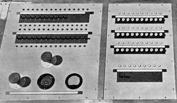
The right hand panel carried the thirty 'punching keys' and two 'first operating keys'. The keys above the faders on the left panel operated studio signalling lights. The transmission positions had keys to operate the studio red lights and the rehearsal positions the blue ones. Both types could also control the green lights. When one of the red or blue light keys were operated, engaged lamps would light on all the control positions, thus indicating to all the operators that the studio was in use. Studios had push-switches which operated a buzzer on the control position, and a further light would indicate which studio had buzzed.
Destination Switching
The destination or C input switching was identical to that for source switching. There were 12 'C' amplifiers, which were fed from 10 sources. The switching was done at the Simultaneous Broadcast position shown on the floor plan as the Trunk Line Switching position. The sources were the 6 transmission control positions and 4 of the 'D' amplifiers. There was an indicator system to show the AME which source was connected to which 'C' amplifier. The 12 destinations included Leeds SB Centre, the Daventry long wave National transmitter and the Brookmans Park transmitter.
Afterthought...
The switching system seems very well thought out but assuming the diagram is correct, it would appear to have been possible to hit two punching keys simultaneously and thus select two sources to the same channel which would have paralleled them on the whole switching system. Also it looks from the pictures as if the channel 'first operating keys' were unguarded and thus if accidentally knocked or caught with the sleeve of an operator's jacket, the source would have been instantly disconnected.
Control Room Mixers
We have looked at the switching facilities associated with the CR control positions, here we look at the mixers. Some positions were equipped with mixers handling four sources, others could cope with only two.
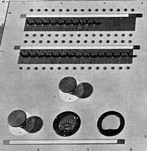
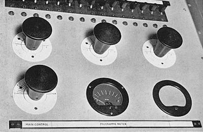
On the four channel mixers (left) the two outer faders each cross-faded between two sources. The central fader took the outputs of the outer ones and handled them similarly. Finally the output of that fader was fed to the main control, lower left.
The main control potentiometer had 26 studs, with a level change of 2dB per stud over most of its range. The final stud before the circuit was broken gave an attenuation of 60dB. The 'cross-faders' used similar pots. As only half of the total travel of the control had to adjust the level of a source from off to maximum, these faders produced a much coarser fade and the final stud before the off position gave an attenuation of 40dB. It was therefore the main fader that was used for level control.
The Studio
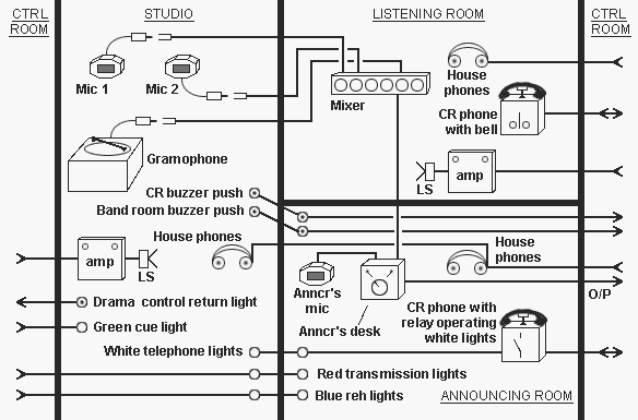
The diagram shows the arrangement of one of the larger studios, equipped with two or more microphones fed into a mixer in the listening room. The mixer had no level meter so was effectively used for balancing only. The output of the mixer was routed through the announcer's control unit. The announcer was able to select between the output of his own microphone and the mixer output. The output of this unit was then fed to the control room where its level could be adjusted at one of the control positions.
Outside each studio was a yellow light which was operated from the House Superintendent's office by the official responsible for the booking of studios. The control room engineers could switch on the studios' red or blue lights (there were separate control positions for transmission and rehearsal) and operate the cue lights. These functions were not available in the listening rooms, though in some cases the announcer was provided with the means of operating a cue light in the studio. This would enable him to cue, say, a conductor, where there was no visual communication.
There were feeds back from CR for the various loudspeakers and headphones - there was no monitoring directly from the mixer or announcers' control desk. Telephones in listening and announcing rooms linked directly to CR. The studio and announcing room had pushes to operate CR buzzers, and, in this instance, a buzzer in a band room. Studios which might be used with the Dramatic Control Rooms also had a means of operating a 'return light' in the DCR as a means of cueing the producer.
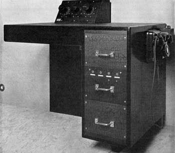
left - A three-channel listening room mixer.
In addition to the potentiometers, the desk contained the necessary microphone
decoupling arrangements and circuitry to reduce the 300 volt high tension
supply to values suitable for operating the condenser microphones. These
mics had their preamplifiers built into the microphone casing.
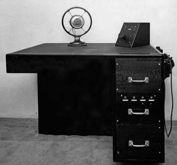
right and below - An announcer's control desk.
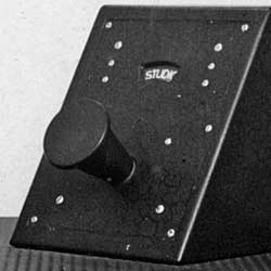
What appears to be a fader knob actually operates the
switch which selects either the announcer's mic or the output of the listening
room mixer. The detail photo shows that the selected source was displayed
in a small window above the knob. Announcements could be made without
the studio hearing them or having to be silent - hence the alternative
name ('Silence Room') for these announcers' rooms. Again, the desk contained
the necessary circuitry for the microphone.
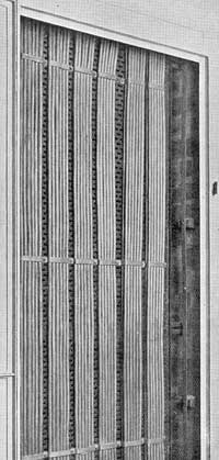
Wiring in the studios ran in iron troughs behind removable wainscoting. Troughs in the concrete floors allowed the cables to run between the various rooms in the studio complex. The cabling back to the control room ran in cable ducts built into the office sides of the studio tower walls. These ducts ran from sub-basement up to the eighth floor. The cables then ran in horizontal ducts into the false floor of the control room.
The Dramatic Control Panels

Although Dramatic Control Panels were by present day standards extremely simple passive mixers, it is very difficult today to work out accurately how they were used and by whom. Part of the problem is that with the outbreak of W.W.II and the economies that had to be made, the DCPs ceased to be used and were probably quickly dismantled. The result was that even people who joined the BBC in the early 1940s only know of them from brief references in books such as the 'Engineering Division Training Manual - 1942'.
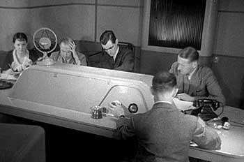
Some clues about how the DCPs were used can be gleaned from the film that was made of Val Gielgud and Holt Marvell's 1934 novel 'Death at Broadcasting House'. Val Gielgud was Director of Productions and played the producer in the film. Holt Marvell was the pseudonym of Eric Maschwitz who was Head of Variety at the time. There are shots of Val Gielgud at what looks to be a
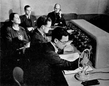
right - Val Gielgud (in the foreground) at the DCP. This appears to be the real thing, not a shot from the film.
Two Quotes from the 1940s:
Engineering Division Training Manual - 1942:
In the years that broadcasting has progressed, producers have become more and more ambitious. For certain shows they demand very many more studios than can be accommodated on the four-channel source mixer provided in the Control Room. So an additional multi-channel mixer, known as a 'production panel', which can have the outputs of the 'A' amplifiers of anything up to 12 or 15 studios connected to it, has been devised. At this panel the producer sits and directs his programme in such a way as to obtain the correct continuity; the final output being fed to the source selector (in the Control Room) on one pair of wires.It is interesting here that the name 'production panel' is used rather than 'dramatic control panel'. This probably came about due to use being made of them by programmes other than Drama productions. Although dated 1942, quite a lot of this manual seems to be based on pre-war practice. In an appendix at the end of the book there is an extract of an address given by Assistant Controller (Engineering), H. Bishop, to the IEE and printed in the IEE Journal in January 1942:
There was a tendency in peacetime for broadcasts to become technically over-elaborate. The use of a number of studios for one production was a growing habit which was catered for to a maximum of 15 channels by a somewhat complicated mixing and control unit known as a "productions panel". With the introduction of local control and the use of larger studios, this multi-studio tendency has largely disappeared and the engineering problems associated with big productions have correspondingly lessened. In any case, the stringencies of wartime broadcasting make such economies essential both as regards accommodation and equipment.This rather gives the impression that even pre-war production ambitions were not totally approved of by the engineering department!
So Why Were Dramatic Control Panels Used?
The simple answer is so that scenes that were supposed to be taking place in different acoustics actually sounded different which meant using different studios for reasons explained below. Also some plays involved an orchestra and chorus and it was not practical to have them in the same studio as the actors, nor was pre-recording an option. (Although two Blattnerphone steel tape recorders were installed on the seventh floor of Broadcasting House when the building entered service in May 1932, they were totally unsuitable for music recording as the speed was not stable. The operator, while watching a stroboscope, had to manually regulate the tape speed.)
It had been realised in 1926 that 'perspective' was important. For example if a play calls for one actor to walk out of a room, then that actor needs to actually walk away from the microphone. If the microphone is simply faded down, the result will not be convincing. The trouble was that studios were in many cases acoustically dead (such as those intended for speech and the effects studios) and those that weren't 'dead' were uniformly treated with sound absorbent material so 'perspective' was very difficult to achieve.
No doubt due to its limited range of acoustics, it was said that the 1932 6A was always recognisable as 6A whether it was supposed to a baronial hall, a living room or a law court. Another problem was that the microphones in use, mainly Marconi-Reisz carbon microphones, were virtually omni-directional except at the higher frequencies, so there was no 'dead' side, which again made it difficult to achieve perspective. In addition even very large studios had a limited number of microphones. For example, 6A which was 36 feet long and 16 feet wide had just 3 independent microphones even though it was used for the musical parts of drama productions and 'concert parties' as well as speech.
The intention was that reverberation could be added as required to produce a different acoustic and there were 5 echo rooms available for this purpose. Without the use of a DCP echo could only be added by the control position engineer in the Control Room. (BBC usage has always been to use the word 'echo' when what is meant is 'reverberation'). This of course meant it was not under the control of the production staff who were responsible for the 'balance' and left to the judgement of the engineer who was only supposed to be responsible for 'control'.
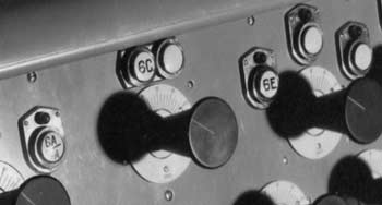
There were 10 studios on the sixth and seventh floors in the so-called 'Productions Group' mainly devoted to drama. The major studio was 6A and its associated dedicated speech studio 7A. 6B, 6C, 7B and 7C were used for speech, 6D and 7D were effects studios complete with water tanks and the other usual effects paraphernalia, 6E and 7E were used solely for gramophone effects and incidental music. (6C, 6D, 7A, 7C and 7D had a totally dead acoustic). These studios were more or less always used in association with the two DCPs and this allowed for one production to be on transmission and another in rehearsal or indeed the simultaneous production of two independent plays.
A Technical Description of the Dramatic Control Panels
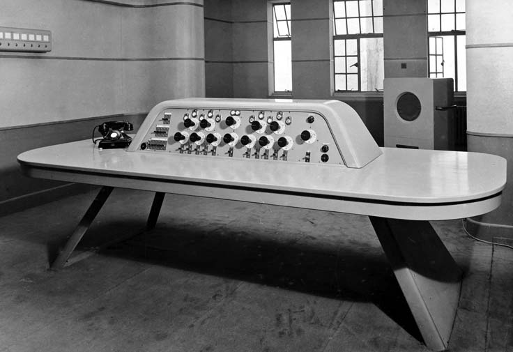
There were two Dramatic Control Rooms situated on the north-west corner of the 8th floor opposite the doors leading to the rehearsal section of the Control Room. Both were wired so that they could be used either for rehearsals or transmissions.
The equipment of the D.C. Rooms consisted of the usual red transmission and blue rehearsal lights and an indicator for return cue lights operated from those studios where orchestras were likely to play in conjunction with dramatic productions. These return cue lights were provided so that the staff in the Dramatic Control Room could be given a cue at the end of a piece of music and the indicator panel can be seen fixed to the wall at the top left of the photograph.
There was a loudspeaker; a telephone for communication with the Control Room; a microphone for giving instructions to artists during the progress of a rehearsal and the dramatic control panel itself.
The 'A' amplifier outputs of the studios required for a production were plugged to the DCP channel inputs in the Control Room at a bay adjacent to the 'A' amplifier bays. It seems likely the engineer plugging up the studios to the DCP would at the same time have switched on the 'A' amplifiers by operating the keys provided on the 'A' amplifier bay. The echo room inputs and outputs were on the same bay as the DCP inputs so any echo facilities needed were easily plugged up. An echo room was fed from a second output on each 'A' amplifier and the echo return was plugged to the fader on the extreme right of the desk.
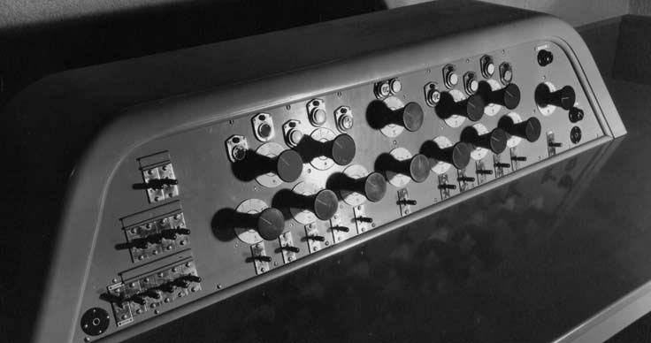
Each dramatic control unit had eleven inputs. Ten of the inputs, each controlled by a separate potentiometer, were divided into two groups of five and controlled by a 'fade unit' or group mixer. The 'fade unit' consisted of a potentiometer that faded out one group of five inputs and faded in the other group when turned through 180 degrees with both groups being at their full volume with the potentiometer midway. The output from this fade unit was connected to one of the inputs of another similar fade unit or two-way mixer, the eleventh source of programme being connected to the second input of this latter fade unit. This was to allow for cases where one studio was used for such items as speech, which may predominate in a dramatic production, and it was claimed that a much quicker and easier fade was available to and from the effects required to be superimposed on the speech. This type of fader seemed to have been very popular in the 1930s but disappeared without trace at the outbreak of war. Mixing was of course entirely passive. The inputs were at -18dBu and although nothing is known about the configuration of the faders there was room for up to 50dB mixing loss so that the DCP output arrived in the Control Room at -68dBu, that is at the same level as other sources.

The two groups of five input faders can be clearly seen. Between them in the centre of the desk are the group fade unit and the 'two way mixer' which faded between the eleventh source and the other ten. The row of keys below the faders
The cluster of keys on the left may have been prehear/talkback keys, or perhaps red or blue light keys; the circular object in the left hand corner of the panel is a headphone jack. From the 'Death at Broadcasting House' film it seems certain that the key under the echo fader at the far right is the producers talkback as Val Gielgud is seen operating it in the film and asking the desk operator to fade up a studio so that he could hear the reply. To the right of this talkback key is a headphone jack; the purpose of what looks like a rotary switch above it is uncertain.
At first glance the DCP seems very simple and the programme chain itself is simple, but when the ancillaries such as talkback, loudspeaker feeds, cue lights etc. let alone red light switching and how the engaged lamps were lit in the Control Room are considered then Edward Pawley's comment becomes more understandable:
It was technically very complicated; once it was set up on transmission, it was impossible to locate faults. The use of many studios on one production meant that staff were dispersed on three or more floors, and it was necessary to have 'studio managers' (in the theatre sense) to keep track of artists and to make sure, not only that they reacted to the right cue light but that they were in the right studio. There was no control of dynamic range on the dramatic control panel, so again there was the problem of the engineer in the control room neutralising the intentions of the dramatic control panel operator.However this is not totally correct because in the book "A Technical Description of Broadcasting House" it says:
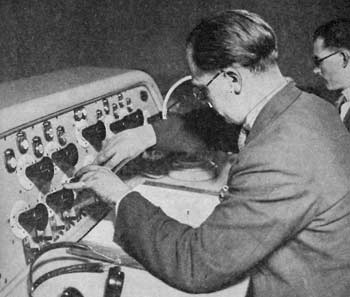
The dramatic control unit in D.C. Room No. 1 is equipped additionally with a main control potentiometer, whereby a producer can, if he wishes, have another official controlling the final output volume actually in the D.C. room; otherwise programmes are controlled at the control positions in the Control Room, or at the cubicle control desks.This main control and a programme meter were set into the rear of the desk, as can be clearly seen in the pictures, right.
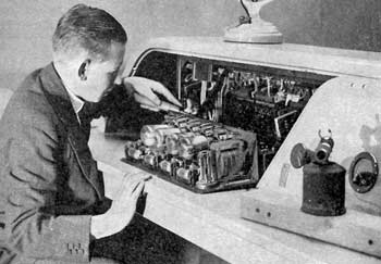
The second photo (probably not taken in 1932, but no later than 1936) shows a rear view of the desk being maintained and clearly shows the meter on the right edge of the picture. The main control can also be seen, though partly obscured by the object in the foreground, which is probably a blowtorch used to heat the engineer's soldering iron. The next photo, which dates from 1937, suggests that the main control and meter were later resited in the box on the left of the panel.

Later developments
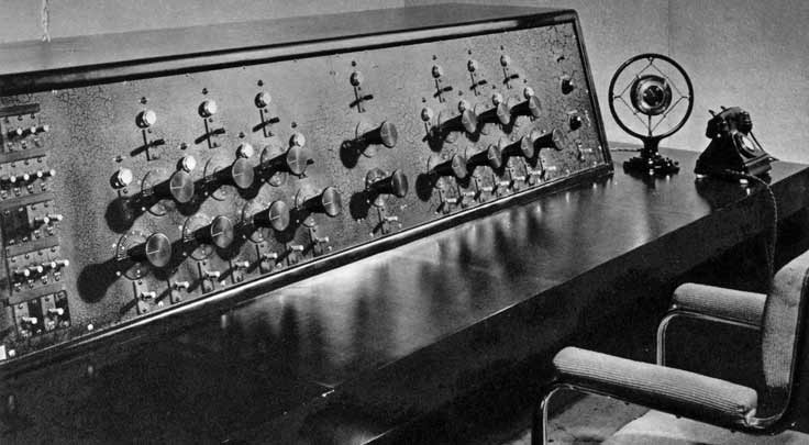
In 1934 a very large drama control panel was built in Broadcasting House. It was originally intended for controlling the multi-source programme in connection with the King's 1934 Christmas Message. Edward Pawley says it was 'so large that it had a 5-ft bench seat on a little trolley so that the operator could ride quickly from one end to the other to reach the control knobs.'
The Music Control Panels
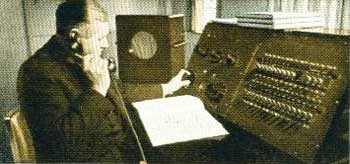
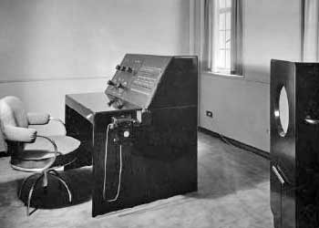
The corresponding desks in Control Room had just four faders, and these music panels should be operationally similar. So perhaps the fifth fader shown in this shot is an echo return, similar to the fader at the right of the DCPs? Another possibility is that this desk had separate faders for each source, rather than the cross-fading system used on the Control Room desks. This would seem to be a better arrangement for controlling music programmes.
The cubicles were switched into circuit by the engineer at the associated CR control position, who was also responsible for selecting the required sources to the channels. A key on the control position operated the cubicle change-over relays. Four of these disconnected the selected sources from the control position and connected them to the inputs of the cubicle mixer. A fifth relay disconnected the output of the control position from its B amplifier, and connected instead the output of the cubicle mixer.
