Eighth Floor
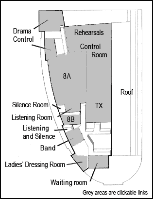
8A | 8B | Band Room | Waiting Room | Dressing Room
The Eighth floor contained the main Control Room, a large studio for orchestral and band music and a much smaller studio for debates and discussions.
The sloping roof on the east side of the building affected the layout of this floor to a considerable extent. As mentioned below, the studio tower stopped one floor down. Two of the four lifts at the front of the building terminated at the seventh floor, too. The Control Room was tucked neatly under the sloping beams.
The Control Room
The Control Room used a relay switching system to enable the complete chain of transmission between any studio and any outgoing line to be set up in the least possible time. There were stand-by facilities and the means of bringing them into circuit without delay should any equipment develop a fault during transmission. Signalling devices showed the approximate positions of any faults. There was much subsidiary equipment, including check receivers, line testing equipment, interval signal equipment and the Greenwich Time Signal apparatus.
The Control Room at this time did actually control the outputs of microphones in the studios. There were no amplifiers in the studios, instead the microphone outputs (or the output of a passive mixer if a studio had more than one microphone) were fed to the Control Room and amplified there.
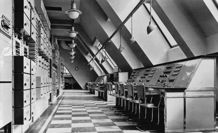
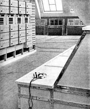
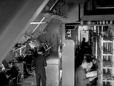
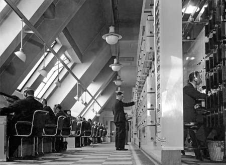
At the far end, beyond the final beam and better seen in the photo, right, were eight desks used for rehearsals.
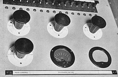
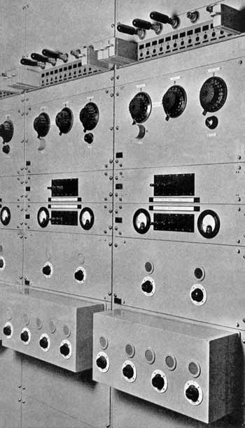
A four-channel fade unit at one of the control positions. The two outer faders each controlled two sources, cross-fading between them. The central fader combined the outputs of the outer ones in the same way and the output of that fader was fed to the main control, lower left.
Although the meter looks like today's Peak Programme Meter, it isn't one. The PPM was not developed till about 1936 or '7 but it did retain the previously designed scale.
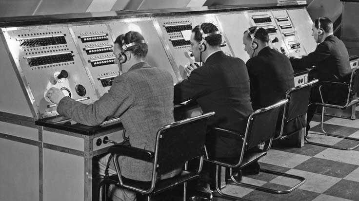
Three of the control positions, seen at Christmas 1935. The whole of this picture appears further down the page.
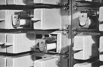
above - Part of one of the relay bays, showing three types of relay used in amplifier switching.
left - Two of the receivers used for checking the quality of transmissions.
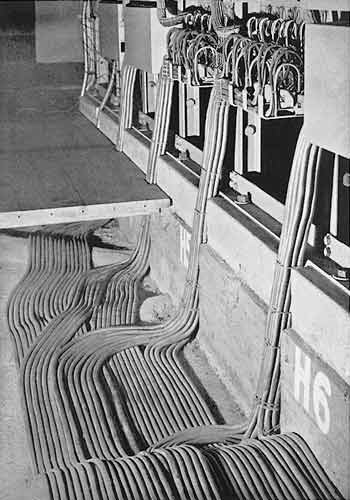
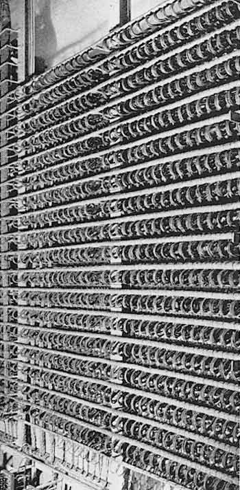
right - Cables in the false floor, ending on terminal strips at the bottom of the 'A' amplifier bays and connecting them with the studios. High output, low impedance Microphones were connected directly to the Control Room through a balanced, screened pair. The cable, which could be up to 1000 feet long, connected through a step-up transformer to an 'A', or microphone, amplifier. High impedance microphones, such as condenser mics, needed a pre-amplifier in the studio, the required power being fed down the microphone cable. The power supply was by means of batteries, in duplicate throughout. The battery room was on the sixth floor.
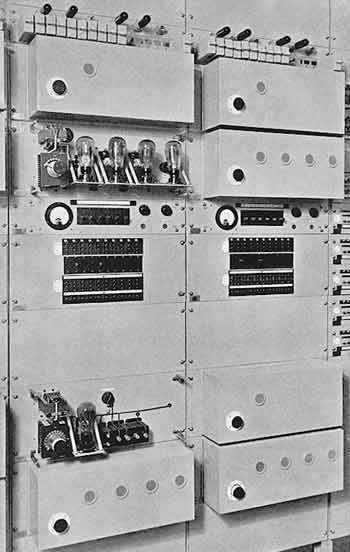
above - Two of the 'B' amplifier bays. The covers have been removed from a 'B' amp near the top of the bay, and from a programme meter amplifier near the bottom.
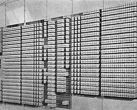
left - The 'B' amplifier input switching relays. The back of part of these bays is seen in the picture above.
Related page
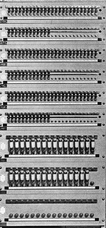
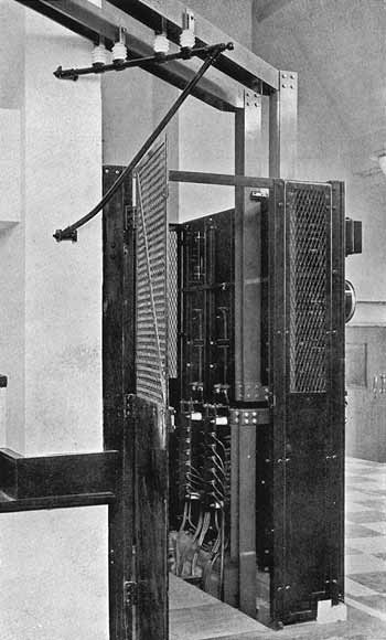
above - The back of the power board, showing the massive low tension busbars supported on the insulators.
left - One of the fuse bays
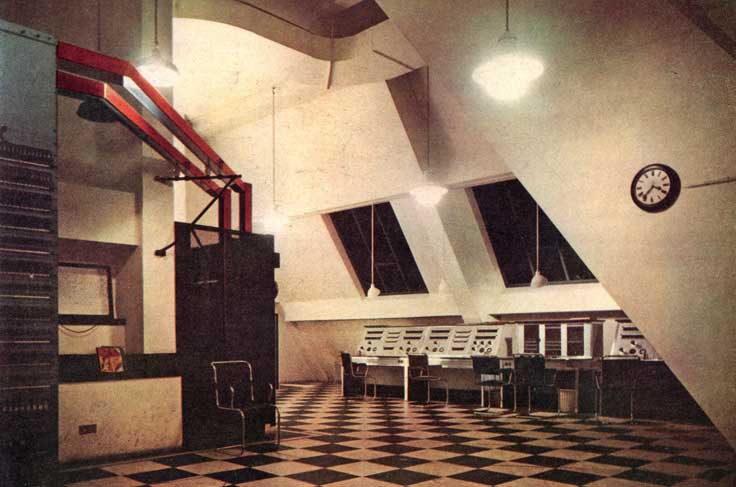
The colour photo shows the rehearsal end of the room.
A contemporary account of this area from the 1934 BBC Year Book describes Work in the Control Room
"the work which fell to the lot of the Control Room Engineers not only in maintaining all the plant but in adding that human element which is so vital to the smooth running of broadcasting."
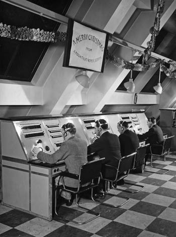
This photo dates from Christmas 1935.
The sign above the control positions reads:
"A Merry Christmas from a room that never sleeps."
A closer view of the desks appears above.
The sign above the control positions reads:
"A Merry Christmas from a room that never sleeps."
A closer view of the desks appears above.
Throughout the "office" day there is a stream of memoranda pouring in from all the various departments of Broadcasting House, such as "Music," "Outside Broadcasts," "Productions" and many others who have an active interest in the work which is required of the Control Room. This flow is centred on a very small but vital section of the control room staff. As an example, there may be a very urgent request for a special microphone lay-out for a "stunt" item to be broadcast in an hour's time - this must be dealt with immediately. Equally there may be detailed instructions for a discussion between speakers in London and New York to be broadcast two months hence, and this requires filing under the date in question. And so it goes on - instructions for the studios to be used for each item of the day's transmissions and for all the numerous rehearsals, with special mention of particular requirements, instructions for recordings to be made by the Blattnerphone, and their subsequent reproduction to the Empire or in the "Home" programmes, details of outside broadcasts, of simultaneous broadcast arrangements, of productions to be controlled on the dramatic control panels, of engineering tests and of a hundred and one other things large and small which ultimately have their direct effect on the programmes as broadcast. Each evening the next day's "operation instructions" must be carefully prepared so that as soon as the first section of engineers comes on duty in the morning each man may know exactly what is required of him for the day. A slip here might easily mean a serious defect in a transmission. For example, a typing error of a D for a C in the special programmes made out solely for the engineers' use might easily cause the control engineer to become highly perturbed at receiving no response from Studio 3D; the speaker concerned meanwhile waiting calmly in Studio 3C for the red light to flick as an indication for him to begin his talk. Dead accuracy here, therefore, is an absolute essential, for once an operating engineer makes a mistake its effect is almost certain to become immediately obvious to the listening public.
Returning to 9 a.m. The fully charged batteries to be used for the day in supplying power to the amplifiers and the signalling and telephone systems have already been connected to the control room bus-bars by the battery engineer, and the discharged batteries, used the previous day, are being recharged by the motor generator sets two floors below the Control Room. The engineers who will be responsible for controlling the programmes are busy calibrating the programme meters on all control positions preparatory to the "line up" test with the Brookmans Park transmitters and the provincial stations. This latter test ensures that all amplifiers in the broadcast chain are adjusted to their correct gain, so that presently the control engineer in London will know that every transmitter taking the programme which he is controlling will be receiving the same input intensity. Similar tests are carried out from the provincial stations to London. Throughout the day all programme meters will be checked from time to time as a safeguard against any discrepancy which may develop...
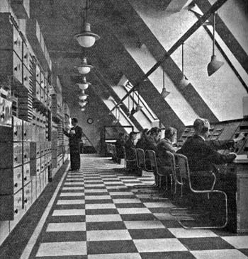
Each broadcast programme has to be continuously controlled by an engineer seated at one of the Control Positions. He has before him a controlling handle, with which he can regulate the volume of the transmission, one or more handles with which he can fade from one programme source to another, a row of keys controlling the signal lamps in all the studios in the building, and a set of special keys by which he is able to set up the particular circuits that he wishes to use.
The engineer has a schedule of the day's programme before him, and his first duty is to set up the circuits for the first two or three studios that will be in use for this programme, by means of the keys on his position. The operation of these keys will switch on the amplifiers required, energise the microphones in the appropriate studios, and bring the outputs of the amplifiers associated with these studios to the fade unit on this Control Position. All this is effected by means of relay switching, the relays being located on the apparatus racks. These relays also cause "engaged" lamps to light on all the Control Positions in both Control Rooms so that the engineer at this position knows that his circuits are set up correctly, and the engineers at other positions know that these particular studios are engaged.
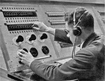
The engineer at the Control Position keeps a continuous check on the programme by means of headphones and maintains the volume within the specified limits, the volume being recorded on a "Programme Meter" on the position. When it is necessary to change from one studio to another or from a studio to an Outside Broadcast, the engineer will set up the second circuit in advance and at the appropriate time will fade from one to the other by means of the fade-unit on his position.
Returning to the article in the 1934 Year Book...
...So we may leave the control engineer who, with his assistant, will be controlling one of the transmissions for most of the day. His assistant, incidentally, keeps a log showing, correct to the second, the time and details of all changes in programme sources, and of all technical faults as heard by wireless, even to a momentary "scratch." This log is of paramount importance to the programme staff in compiling their statistics, in addition to its primary engineering value.
The S.B. (simultaneous broadcast) engineer starts his turn of duty by checking up all programme and technical arrangements with the nearest provincial S.B. centres, for he will be responsible for ensuring that they receive the correct programme at the correct time, and for most of the day he will be dealing with at least three separate transmissions. He also sees that the Greenwich Time Signal is broadcast according to schedule.
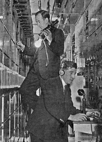
Rather similar to the work described above, but very much more complicated, is the preparation of the circuits for dramatic productions using many studios. As will have been gathered from the article on "The Dramatic Control Panels" on p.385 of the 1933 Year-Book, the possible combinations of circuits are endless. The normal lay-out requires usually some three studios, together with echo on perhaps two of them, an effects and a gramophone studio - in all some seven sources of "programme." All these have to be plugged up to the correct positions on the panel as indicated by the producer. Cue light circuits, loudspeakers in listening rooms, headphone circuits, talk-back circuits to loudspeakers in the studios in the case of rehearsals, and probably circuits for recording purposes have to be set up and thoroughly tested before the producer can start his rehearsal. Such an intricate linkage requires the most
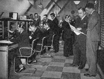
A group gathers near the supervisory positions on
Christmas Day 1933. Engineer-in-Charge, A. G. Dryland, is on the right.
In addition to those already mentioned, there are the engineers sitting at the supervisory positions dealing with the internal telephonic inter-communication and the engineers checking the transmission quality by loudspeaker three floors below, and the senior control room engineer who is the mainspring of the whole section of engineers.
But this is not the whole of the picture. Side by side with what might be called the main engineering routine there is the work at the Blattnerphone recording apparatus (now largely used for Empire Broadcasting as well as for rehearsal purposes), that connected with gramophone recording, running the television transmissions, and the ultra short-wave transmitter, not to mention the labour of maintaining and cleaning this vast amount of apparatus and wiring, the storage and issue of spare parts, and the testing of the valves actually in circuit (it takes one man a month to do them all).
Finally, there are the engineers responsible for broadcasting the programmes to the Empire throughout the night, and who in their spare time carry out most rigid tests on the loudspeakers which are used in the various listening rooms and studios, in order to maintain a high standard of quality of reproduction.
Add to all this the work entailed in testing out new types of microphones, control room amplifiers, valves, etc., and it will be admitted that the London Control Room and its staff must needs be a large and complex organisation.
Another article describing work in the Control Room
This article appeared in the very first, June 1936, issue of the Ariel, the BBC's in-house magazine. The introduction reads:
"An exclusive and authoritative article describing - for first time - the working of the Control Room, that 8th Heaven of Broadcasting House. We hope to continue this attempt at explaining our jobs to each other. When we get to the end, we shall have described - broadcasting!"
A RED LIGHT flicks three times, in Studio 3B. 'Quiet, please', and the red light comes up steadily. 'This is the National programme.'
Who is working this red light? It is wired up to the Control Room on the eighth floor. There at his control position sits the engineer, and in front of him is a key by which he operates the red light in the studio below. When he first flicked three times, he received back at his control position a buzz from the announcer, and at the same time a green light appeared in front of him to indicate from which studio the buzz had come. The announcer's button works the buzzer and the green light simultaneously. On this return signal the engineer fades in the studio and puts on the red light permanently.
'Fades in the studio'? What does this mean? We have now finished with the signal lights and their circuits until the end of the transmission. Now what about the programme circuit, the actual circuit on which the voice of the announcer leaves the studio and ultimately leaves Broadcasting House on its journey to the transmitters? The microphone has picked up the voice and turned it into varying electrical impulses or speech currents, as they often call them, and the rest of the problem is one of amplifying them and arranging that they ultimately reach the right transmitter-National or Regional or whatever the transmitter may be. They have been known to reach the wrong ones, but on very rare occasions!
Leaving the studio, the wires run in lead-covered cables through the wall of the studio tower and up the outside of it - behind those metal doors which you see on the inside of the passage on each floor - arriving at the Control Room above, where they are connected to the first or 'A' amplifier. There is one amplifier to every studio, and if you stand in the Control Room you will see down the length of the room, like vast book-cases in a Public Library, the tiers of amplifiers. Each one bears the name of its appropriate studio - for instance 3B, CH, BA or whatever it may be. They are all painted grey. This 'A' amplifier is not permanently switched on, but has been switched on by the engineer before he flicked the red light. He switched on by pressing the 'punching-key', which is just a button on the control position. In setting up this connection the engineer has at the same time switched on the second, or 'B', amplifier which is always associated with the particular control position at which he is working. This Second or 'B' amplifier is in a way his own private amplifier, in the sense that it is associated only with his control position: whereas he can select any 'A' amplifier with its associated studio by pressing the appropriate punching key. In fact he can select two or even four 'A' amplifiers with their associated studios, and mix or go over from one to the other so as to secure a smooth change from one programme to the next. Now we can understand what this engineer does to 'fade in the studio'. For on each control position is fitted a knob which controls the volume or amplification allowed to pass from the 'B' amplifier. This can be smoothly varied from zero to a maximum. When he turns the knob, he 'fades in', so 'fading in' is exactly similar to turning on the tap gradually.
So this control knob has a double function. It turns on the programme in the first place: and then, once it is turned on, it regulates its volume, because it controls the 'B' amplifier. The correct limits of volume are indicated by a meter, of which the needle is swinging the whole time in front of the engineer at his control position.
His responsibility ends at this point. He has ready a complete programme, but it is not his job to send it out to the world. (There are five other control positions, making six in all: and so our engineer may be one of six, each ready with a complete programme. Where do they go? Now read on.)
The programme going on its way from the 'B' amplifier and so out of the control of the first engineer, has next to be directed to the transmitters: actually to the telephone lines which will take it to the transmitters, it may be at Brookmans Park, at Droitwich, or elsewhere.
The programme is connected through from the 'B' amplifier to the next ('C') amplifier from a switching position known as the S.B. (Simultaneous Broadcast) desk. Here sits a second engineer. He can accept any one of six programmes coming from the six control positions - and send any one of them out to any one transmitter or number of transmitters. He can also send it to the G.P.O. Radio Terminal for a transmission over the P.O. Radio Telephone circuits, to Canada, Australia, New Zealand, etc., and also over the continental circuits to any country in Europe. Each outgoing line, whether it be to one of our own transmitters or to the P.O. Radio Terminal, has its own 'C' amplifier.
Thus our programme, coming from Studio 3B, has gone first through the 'A' amplifier permanently associated with that studio; then through the 'B' amplifier, which belongs to the control position; and now through the 'C' amplifier, which is associated with the outgoing line to the transmitter. From the output of the 'C' amplifier it goes out in a cable to the P.O. Trunks exchange. Although these wires pass through the P.O. exchanges, they are not dealt with as ordinary telephone lines, but they are private lines, so that the programme is not subject to an interruption of 'Three minutes, please.' And so at last the programme arrives at the transmitting station, where, after passing through more amplifiers, it finally reaches the transmitter itself. Until this point the programme is neither wireless nor broadcast. It has been guided along wires throughout its course, and from now on it is truly broadcast over the ether.
So far we have been watching a programme that was dealt with entirely in the Control Room. It may be, however, that part of the work of the Control Room has been segregated, as it were, to some quieter room; and that the actual work of combining several parts of one programme is being carried out at a D.C. (Dramatic Control) panel.
In a dramatic presentation, for instance, several studios may be used, and then the output of each studio, the moment it arrives in the Control Room and has passed there through its 'A' amplifier, is directed down to the D.C. panel, at which is the producer's assistant.
The actual mixing is rather like mixing the hot and cold water in a shower. Each control knob on the panel is connected to a particular studio for this production. In one of these D.C. panels (D.C.3) there are as many as fifteen control knobs. It was specially designed to cope with the complicated arrangements on Christmas Day.
The mixed output is led back to the Control Room, where in fact an engineer at a control position deals with it exactly as he would deal with a single programme from a single studio. He 'fades in' not 3B this time, but D.C.3.
So far we have been dealing with programmes originating entirely in Broadcasting House. Any programme that doesn't, arrives at Broadcasting House by a telephone line. (This may be a trunk line, bringing a programme from a distance, either from our own Regional studios or from the Continent, or even further afield, or it may be a local circuit from Maida Vale or a London O.B. point). The programme arrives in the Control Room and passes through a 'D' amplifier. This amplifier serves somewhat the same purpose as the 'A' amplifier serves for a programme coming from a studio. The engineer at a control position can deal with this programme in exactly the same way as if it originated in a studio in Broadcasting House.
There's one further thing to say about the volume control of a programme. We have described the case where the volume is controlled at the control position in the Control Room, and this is correct for the News and generally for Talks. But in most other programmes the volume control is not carried out by the engineer at that position: he switches the programme to a special cubicle arranged for this purpose, where some one can listen to it in peace and quiet, on a loudspeaker instead of on headphones. This is particularly desirable in the case of Symphony Concert programmes, where the volume control demands special knowledgc of music.
This is a very brief description of the main work of the Broadcasting House Control Room. We have said nothing of the eight rehearsal positions, the distribution arrangements for working Loudspeakers in the Listening Rooms and throughout the building, the talk-back facilities on the D.C. panels and elsewhere, the Echo Rooms, the Effects Room, the Time-Signal, and the interval-signal apparatus, the check receivers, the line termination position, or the complication of fitting together a large number of programme items to form one or more smooth-running programmes.
And then remember that the Broadcasting House Control Room is not the only control room, and that all the control rooms together are a small part, although an important part, of the Engineering Division. Did you know that the members of the Engineering Division number over 1,000?
Dramatic Control Rooms
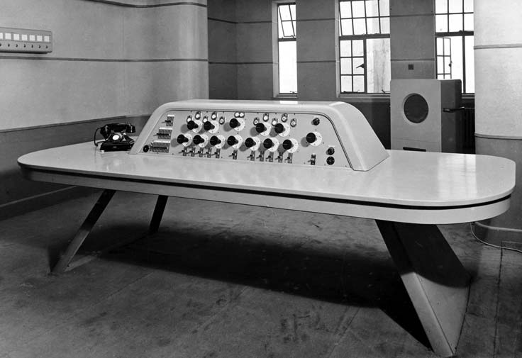
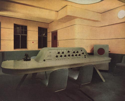
The two dramatic control rooms - No.1, above and
left, and No.2, below. The desk was framed up in stream-lined
tubular steel sections, supported and fixed to the floor at one end by
two free standing legs. At the other end the legs were enclosed to form
a duct for the cabling which rose from a floor duct. The panel enclosure
and table were in mahogany laminwood and cellulosed a lavender grey. The
walls were acoustically treated with half-inch insulwood building board.
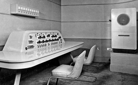
The same room could be used for both rehearsals and transmissions. They enabled the mixing of up to eleven studios for one transmission. In this way, it was said, stage management was facilitated in the studios and a completely mixed programme was passed on to the Control Room for distribution to the transmitters.
The 1933 BBC Year Book explained: "The object of the D.C. Panel is to enable the producer to combine at will the output from various studios. This is necessary, since it would be difficult to produce a play other than a very simple one in one studio alone. For example, where a play includes dramatic speech, crowd noises, incidental music, special sound effects, and special effects obtained from gramophone records, it would be impossible to produce all of these things in one studio. The various types of effects are therefore produced each in a separate studio and combined by the producer by means of the D.C. panel."
Studio 8A
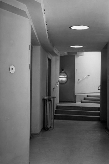
Standing a little to the left of the southern entrance
to the Control Room gave this view, left, of the corridor leading
to the two studios on the eighth floor. The circular sign to 8B is on
the wall between the two flights of stairs. The corridor was lower than
most due to pipework and conduits above. Head room was maintained with
the use of lights flush to the ceiling. The walls were pale yellow and
the floor was a cream coloured composition.
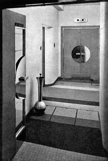
Going up the second flight of stairs led to the outer doors of Studio 8A, right. The inner studio doors are ahead and to the left another door led to the listening and silence rooms. The vase-like object is an unspillable ash container. It was made from bronze, the upper half was satin-silvered and the lower part of the weighted base had a gunmetal finish. Turning the knob released the lower part for cleaning.
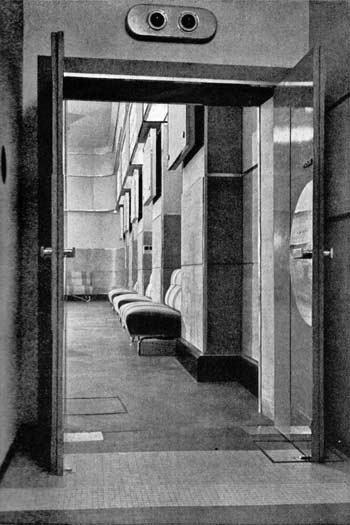
Left - Looking north through the opened inner doors.
8A was designed by Serge Chermayeff. It was used for small orchestras, brass and military bands, musical comedy and revues. Because of the sloping mansard roof on the east side of BH it was not possible to build the studio tower to the eighth floor level and 8A was therefore positioned right over to the west wall of the building which allowed some circular windows to admit daylight - the only studio in the building where natural light penetrated.
The studio was 51' x 33' x 16' high, a volume of 27,000 cu. ft. The reverberation time was 1.1 seconds.
The colour view below is looking northwards from the door and the shot below it was taken from the other end.
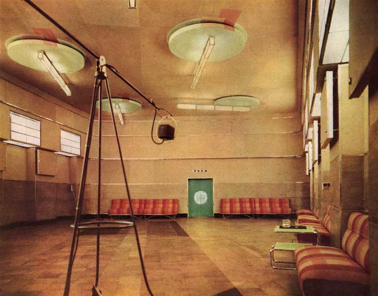
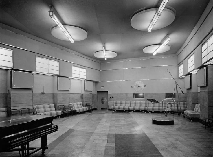
The walls had a protective birch plywood dado to the height of five feet. The ebonized skirting was removable to allow access to the microphone cables within - this feature was used in all the studios. The bands above the dado were covered with untreated building board the edges of which were protected by aluminium strips. The ceiling was painted in an apparently haphazard pattern. The doors were faced with oak ply painted bright green with polished aluminium fittings. The floor was laid with square cork tiles in five shades ranging from light buff to black, again in a random design. A large circle in the design suggested a grouping area for the musicians.
Artificial light came from wall boxes which also covered the circular windows on the west side. Long strip lights were mounted on the circular ventilation pans on the ceiling.
Chromium-plated tubular steel-framed settees covered in striped coral pink tweed were designed by Chermayeff as was the conductor's rostrum.
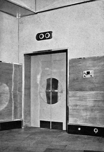
left - The south entrance doors. A microphone
socket can be seen mounted on the skirting and on the panel above a socket
for headphones.
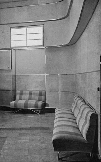
right - A curving corner showing how the bands of material of different widths were run unbroken round the walls, an effect emphasised by the protective metal strips.
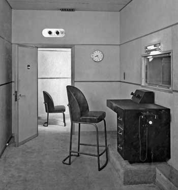
left - The Listening Room for Studio 8A. The mixer handled three sources - the single microphone that 8A could employ, plus two gramophone points.
Through the open door can be seen the Silence Room, where announcements could be made during an interval in the studio.
8A was the first studio to be completed and the first musical broadcast from BH came from there. It was on 15th March 1932 and featured Henry Hall and the

Band Room
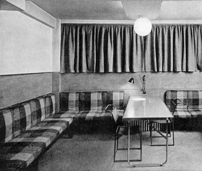
Like the studio, the band room had a protective dado
of birch plywood. The benches were of ebonized wood covered with standardized
removable cushions covered in black and grey tweed cushions. The composition
floor was red.
Studio 8B
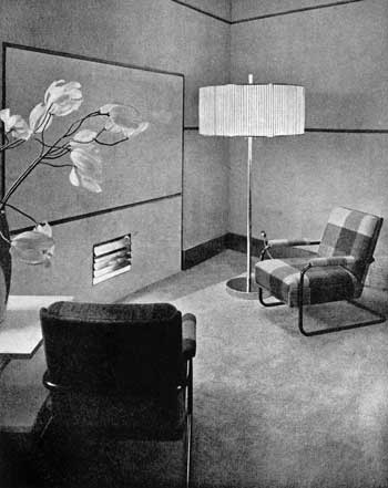
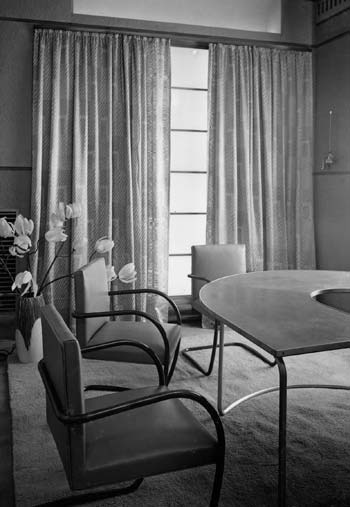
The tall artificial window gave a sense of airiness and the 'fire' threw a pleasant glow over the floor and lit up the satin copper colour of the metalwork and skirting. A natural wool rug covered much of the floor.
8B was 16' x 13' x 10' high, a volume of 2,100 cu. ft. The reverberation time was 0.45 seconds.
Waiting Room
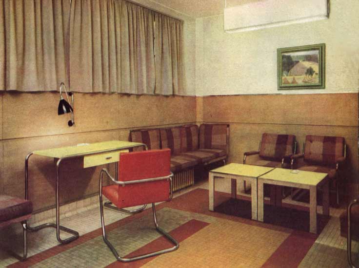
Again the work of Chermayeff, the waiting room had floor and skirting covered with small square tiles arranged in a carpet-like pattern. The settee cushions and the armchair upholstery were tweed. Lighting was provided by two trough lights suspended above the lemon-yellow-topped tables. On the end wall was a reproduction of John Nash's 'The Cornfield.'
Ladies' Dressing Room
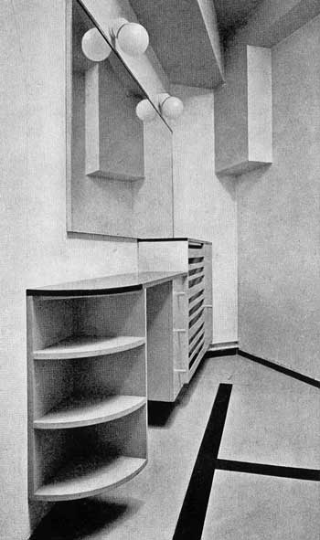
This was an oddly shaped room with intruding beams and casings. The photo, left, shows a radiator cover, the dressing table and a mirror.
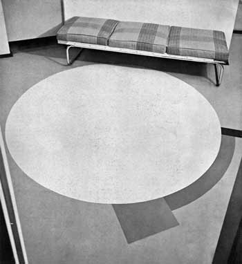
above - The circle in the inlaid rubber floor was white, the surround was pink-grey with accents of red. The settee was covered with coral red fabric and the walls were cream-white.

